
Rotary Tool and 3D Print Finishing
Deburring 3D Printed Edges: A Mini Rotary Tool Workflow
A practical guide to deburring 3D printed edges: remove local excess with a mini rotary tool, preserve corners, finish by hand, and check the fit.
Quick Answer
Deburring 3D printed edges means removing plastic that projects beyond the intended outline, while preserving the edge itself. A mini rotary tool can help with isolated, accessible protrusions on robust FDM parts. Use a file or supported sandpaper for straight reference edges, delicate corners and final blending. Establish the original shape before making any powered contact.
Buyer Takeaways
- Identify the intended edge before removing a burr.
- Preserve mating faces, corner points and wall thickness.
- Test the exact filament and approved accessory together.
- Stop powered cleanup early and inspect the cooled part by hand.
Begin with the edge you want to keep
A rough bracket, display base or tray can have several different problems along the same perimeter. A short support remnant is excess material. A chipped corner is missing material. A deliberately sharp design edge may feel uncomfortable without being a printing defect. These are different decisions, even when they occur within a few millimeters of one another.
Compare the part with the model or an undamaged section of the same edge. Look along it under side lighting. Identify which face provides a reference and whether the corner must remain square for assembly. Do this before choosing an abrasive: once an edge has been rounded, removing more plastic cannot put the original corner back.
For a decorative base, the endpoint may be a clean silhouette. For a sliding lid, it is unobstructed movement with the designed clearance. Write down that endpoint in ordinary terms. “Remove the raised nub beside the slot” is more useful than “make this whole edge smooth.”
Match the contact shape to the defect
A small approved abrasive head can target a distinct raised area where the surrounding wall is substantial and visible. It needs room to approach without the chuck, shank or unused part of the head touching the model. An inside curve may offer useful access; a narrow square corner often does not.
For a long straight edge, a fine file or abrasive paper backed by a flat block gives a larger reference surface. Work along the intended line and check both adjoining faces. Loose paper wrapped around a fingertip tends to follow and soften a corner, which is useful only if a rounded edge is actually wanted.
Do not assume that the smallest pointed head offers the best control. Its concentrated contact can cut a groove beside the burr. Nor should a polishing wheel be used as the first answer to a raised obstruction: changing the sheen does not establish the correct geometry. Choose the method whose working surface fits the task.
Technical Explanation
What changes during cleanup
An edge is the intersection of two surfaces. Removing a burr preserves that intersection; rounding it deliberately changes both surfaces near the corner. Keep the design or an intact neighboring section as a reference, and judge the result by the required shape and fit rather than by smoothness alone.
Secure the print before breaking away support
Let the print cool and remove it from the build surface according to the printer maker's instructions. Inspect for split layers and cracking around the edge. A weak wall should not be forced into a clamp or treated as a sound part simply because the outer finish looks acceptable.
Wear eye protection while removing large supports with suitable hand tools. Break the support into manageable sections instead of twisting it against the model. Support the neighboring body, leave a stubborn small attachment for later, and keep the cutting direction away from your hands.
For finishing, use padded jaws or a fixture on a robust portion of the print. Position the edge so the working point stays visible. Arrange extraction suitable for fine plastic dust and follow the filament and abrasive instructions for respiratory protection. Keep jewelry, hair and loose clothing clear of the rotating area. If the fixture conceals the burr or flexes the shell, reposition before proceeding.
Make a meaningful trial on matching scrap
Use a failed print or coupon from the same spool, ideally with the same wall thickness and a comparable edge. Secure it in the same way. Testing a thick block does not show how an unsupported lip will react.
With the tool off and charging power disconnected, check the accessory's mounting, condition, shank size, material suitability and permitted working surface. Use only a tool setting allowed by both tool and accessory instructions. An accessory's speed limit remains binding even if the pen can run faster. Where the material or head is not documented, obtain suitable instructions or use a hand method.
Try light, brief contact, then stop to inspect. Look for a smaller protrusion with the original edge still legible. Smearing, chatter, a slipping shaft or a new notch means the setup is not ready. A successful trial supports that combination only; it is not a universal setting for all PLA, PETG or abrasive shapes.
Approach the high spot without recutting the outline
Work only on the protrusion identified during inspection. Keep contact short, lift away and examine progress with the tool stopped. Reposition the part when approaching the next face would hide the contact point. Do not continue around a corner in one uninterrupted movement merely because the burr follows the perimeter.
Leave the final trace slightly proud and change to the hand tool that matches the reference edge. This gives you a controlled transition from local removal to a continuous line. Check the corner from both directions rather than judging only the face nearest you.
PLA can soften from friction; PETG requires its own trial rather than a faster version of the same recipe. Thin features have less margin for either heat or mechanical damage. If the print smears, flexes or begins to lose its intended outline, stop and reassess. This workflow concerns rigid, unfilled FDM plastics; flexible and filled grades need separate guidance.
Check fit before primer or final assembly
Remove dust with a method suitable for the part and debris, then examine the edge under side lighting again. Avoid blowing fine dust toward your face or into printer mechanisms. Check for a remaining lip, fresh scratches, exposed infill and an unintentionally rounded corner.
Dry-fit the part without forcing it. If it still binds, identify the actual contact point before removing more. A warped panel or undersized opening cannot be diagnosed just by noticing that one edge feels rough. Keep electrical components away during abrasive work and clean the part before reinstalling them.
For painting, blend local scratches by hand and follow the primer maker's surface preparation instructions. A recessed scar may need compatible filler; sanding the whole face down to that scar unnecessarily thins the wall. Do not hide a crack beneath filler and call the part structurally repaired. Decide whether the remaining defect is cosmetic or requires a new print.
What to confirm when choosing the H102
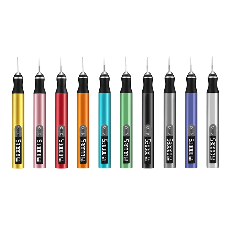
The ToolQeen H102 is a pen-shaped cordless engraving tool with a listed 59 g body, five adjustable gears, a digital display and a 2.35 mm metal chuck. For local edge work, the slim form can help position the working point, while the display makes an approved setting easier to identify and repeat. These features do not replace a fixture or a scrap trial.
The product page lists plastic carving and model making, and a maximum speed of 30,000 RPM. It does not publish a minimum speed, gear-by-gear values or a filament-specific abrasive chart. The maximum is therefore not an edge-deburring recommendation. Likewise, the stated 30 accessories do not establish which head is appropriate for your print.
Before ordering, ask about the specific 2.35 mm accessory, its plastic suitability and instructions. ToolQeen currently presents a sourcing and sample inquiry route; individual makers should confirm single-unit or sample availability rather than assume a retail checkout.
Frequently Asked Questions
Frequently Asked Questions
Should every printed edge be rounded?
No. Some edges locate a lid, align an assembly or preserve a model's outline. Remove an unintended projection first. Add a rounded edge only when the design and intended use allow that change.
Can a rotary pen straighten a bowed edge?
Local deburring does not correct the overall geometry of a warped part. Check the model and print before grinding. Removing enough material to disguise a bow may leave an uneven or undersized wall.
Why does the edge look white after cleanup?
Abrasive scratches or mechanical stress can change its appearance. Clean and inspect the cooled surface. Do not keep grinding just to restore color; determine whether the mark is cosmetic or accompanies cracking.
Is a 1/8-inch accessory a direct H102 fit?
No. The H102 listing specifies a 2.35 mm chuck. A 1/8-inch shaft is a different size. Do not force it or improvise a sleeve; confirm an explicitly supported accessory connection.
When is hand finishing the better first step?
Use it when only a faint lip remains, the edge is straight and dimensionally important, or a powered head cannot approach without touching a neighboring feature. A motor is optional, not a required stage.
Final Buyer Recommendation