
Rotary Tool and 3D Print Finishing
Cleaning Openings in 3D Prints: Slots, Recesses and Cable Passages
A guide to cleaning openings in 3D prints without losing their shape: assess slots and recesses, remove minor obstructions, and check component clearance.
Quick Answer
Cleaning openings in 3D prints means identifying what obstructs an existing slot, recess or passage before enlarging anything. A mini rotary tool may remove an accessible local burr on a substantial rim. Use hand files for straight walls and controlled corners. Treat undersized holes, deep blind passages and precision fits as separate design or machining problems.
Buyer Takeaways
- Inspect both ends of an opening before changing its size.
- Remove local obstructions without redesigning the passage by eye.
- Preserve corners, locating shoulders and nearby thin walls.
- Clean thoroughly before fitting cables or electrical components.
Locate the actual obstruction
A cable pass-through or mounting recess may look open but still catch at one rough entrance. Another may be clean at its rim yet too small through its full depth. Before finishing, inspect from both sides where possible and compare the opening with the model and intended component.
Look for support remnants, stray filament, an uneven bridge underside and a widened first-layer edge. Distinguish a raised obstruction from a wall that was designed or printed too close to its opposite side. A rotary pen is a possible cleanup tool, not a substitute for deciding which dimension is wrong.
Keep the component out of the print while investigating with abrasives. For an enclosure, remove electronics and cables so dust cannot collect in connectors or mechanisms. Record any shoulder, keyway or corner that locates the component. Those features may be more important to function than a uniformly smooth interior surface.
Match the method to the opening's geometry
For a straight slot, a suitably shaped fine file lets you work along one wall while observing the opening. Supported abrasive paper suits a broad accessible recess. A cylindrical rotary head may suit a local defect on a sufficiently large curved rim, but it can also round corners or turn a circular entrance into an oval.
Check the approach with the tool switched off. The working head must reach the defect without its shank, chuck or opposite side contacting another wall. Do not push into a blind passage where you cannot see what is being removed. A long reach is not permission to extend an accessory beyond its specified mounting depth.
If the job requires an accurately sized hole, thread or bearing seat, use the appropriate documented design and finishing process. This guide does not recommend drilling with the H102, reaming with an abrasive head or using a cutting disc sideways to widen a slot.
Technical Explanation
What changes during cleanup
An opening has an entrance, internal walls and often a locating surface. Making one region smoother can change its size without fixing another region's obstruction. Treat each surface separately and inspect the fitted position, not merely whether the component can be pushed through.
Remove loose support and secure the rim
Wear eye protection while removing large support pieces with suitable hand tools. Work from an accessible end and separate supports into small sections. Do not force a whole support plug through a narrow passage; it may wedge against the wall or break a locating feature.
Stop if removal would require levering against a thin rim. A remaining small attachment can be evaluated separately. A broken corner or split wall creates a different repair problem and may affect the part's ability to retain the intended component.
Secure the print at a substantial area using padded jaws or a fixture. Place the opening where its working edge is visible and keep fingers outside the tool path. Arrange fine-plastic-dust extraction and follow the filament and accessory instructions for respiratory protection. Do not hold a cable inside the opening as a guide while grinding around it.
Test the setup on a comparable passage
Use matching scrap with a similar wall, rim and opening. An accessory that behaves acceptably on a flat coupon can contact two surfaces at once in a narrow slot. The trial should reproduce that clearance issue rather than only the filament color.
With the pen off and charging disconnected, check the head for damage, confirm the shank and mounting, and review plastic suitability and speed limits. Use an allowed setting for the tool and accessory. If the head is not documented for the operation, select another supported method before touching the finished part.
Make brief, light contact on a local projection. Stop and inspect the cooled result. Look for preserved corners and an unchanged opposite wall as well as a smaller burr. Smearing, chatter or a new groove shows that the current approach is unsuitable. Change one variable at a time or return to the file; pressing harder is not a diagnosis.
Finish one obstruction, then reassess the fit
Approach only the identified excess. Lift away frequently and inspect with the tool stopped. Avoid sweeping around the whole opening to make the finish look consistent. That can remove sound material from the side that already fits.
Switch to hand finishing while a small raised trace remains. A fine file should follow the intended wall; abrasive paper should be supported so it does not wrap around and soften a locating edge. Keep a visible reference for the original corner. Where clearance is tight, a small untouched cosmetic mark may be preferable to an enlarged opening.
Clean the passage before gently checking the component or cable. Never force a connector through to prove that it fits. If it still catches, find the point of contact and compare the dimensions again. Repeatedly removing material from the entrance will not correct a problem farther inside or a misaligned printed channel.
Inspect for service use, not only easy insertion
For a cable passage, check the whole accessible rim for a sharp residual lip after cleaning. A cable that passes through once is not evidence that its insulation will remain protected in use. Follow the device design for grommets, edge protection and strain relief; an abrasive finish does not replace those features.
For a removable component, confirm its seated position and retaining features. Over-cleaning a shoulder may let it move even though installation feels easier. Inspect for a thinned wall, exposed infill or cracks around the opening before deciding the part is ready.
If paint is planned, protect dimensions and use the coating maker's preparation instructions. Coating buildup can reduce clearance. Check fit at the appropriate stage and keep debris or masking residue out of the passage. For safety-critical, load-bearing or tightly toleranced assemblies, do not rely on an improvised cosmetic cleanup procedure to establish performance.
Check the H102 against the actual access problem
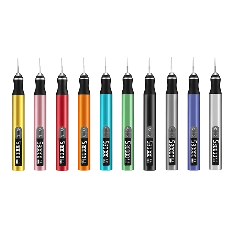
The H102 has a listed 2.35 mm metal chuck, a pen-shaped body and five adjustable gears with a digital display. These details matter when positioning a compatible head beside a visible entrance burr and identifying a tested setting. They do not establish a permitted drilling operation or a guaranteed minimum passage diameter.
ToolQeen lists plastic carving and model-making applications. The accessory count is 30, but dimensions and material suitability for each head are not published on the page. Request the exact accessory identification and instructions for your opening rather than selecting by the total number of pieces.
The listed maximum speed is 30,000 RPM; the minimum and each gear's RPM are unspecified. Confirm that the proposed setup supports the filament and operation within its allowed range. The product page offers a sourcing inquiry route, so individual makers should check sample or single-unit availability before assuming they can order one directly.
Frequently Asked Questions
Frequently Asked Questions
Can I use the H102 to drill out an undersized hole?
This guide does not establish that operation. The public listing does not provide the drilling setup needed to recommend it. Use a documented process appropriate to the hole, material and required tolerance, or revise and reprint.
Why does a connector still catch after I smooth the entrance?
The internal passage may be undersized, rough or misaligned. Inspect beyond the rim and compare the component envelope with the model. More removal at the entrance alone may only weaken the surrounding wall.
Should a square slot be rounded for easier assembly?
Only if the design permits it. Square corners may locate a keyed component or define its seated position. Preserve them while removing isolated burrs, and use an appropriate hand file where geometry matters.
Is a smooth cable hole enough protection for wiring?
No. Use the edge protection and strain relief specified for the device. Cleanup can remove an obvious protrusion, but it does not establish resistance to cable motion, abrasion or other service conditions.
Can I finish an enclosure with the electronics inside?
Remove the components before abrasive work and clean the enclosure thoroughly afterward. Dust and fragments can enter connectors and mechanisms. Do not use an installed component as a grinding guide or sacrificial stop.
Final Buyer Recommendation