
Rotary Tool and 3D Print Finishing
Preparing 3D Prints for Gluing: Rotary Cleanup Before Assembly
A practical guide to preparing 3D prints for gluing: identify high spots, preserve mating faces, clean away debris, and check alignment before bonding.
Quick Answer
Preparing 3D prints for gluing starts with a dry fit, not an abrasive. Find the raised support remnants that prevent the parts from seating, remove only that excess, and preserve the faces that control alignment. A mini rotary tool can help on accessible, solid features; a flat sanding block is usually better for broad mating faces. Clean and inspect both pieces before applying adhesive.
Buyer Takeaways
- Correct a visible high spot before changing an entire joint face.
- Keep alignment pins, shoulders and glue-contact surfaces at their intended dimensions.
- Match adhesive preparation to the exact filament and adhesive instructions.
- Test the accessory on scrap, then repeat the dry fit after each small correction.
Start with the joint you actually printed
Two model halves can look ready for glue while touching at only a few unwanted points. A support nub on an internal ledge may hold the whole seam open. A first-layer lip may prevent a locating tongue from entering its groove. Grinding the visible outside seam will not fix either problem before assembly.
Place the cooled, clean pieces together without glue and without forcing them. Look at the joint from several sides. Note where the seam closes, where it opens and whether one piece rocks. Compare those observations with the model or assembly instructions. A designed glue gap is different from a gap created by an obstruction.
This guide concerns ordinary rigid FDM model parts. If the print has split layers, a crushed pin or a visibly warped bonding face, decide whether to reprint before spending time on cosmetic cleanup. Removing more plastic cannot restore missing material or make a weak print sound.
Separate high spots from gaps and alignment errors
A raised defect interrupts an otherwise plausible contact surface. A recessed scar is missing material. The first may benefit from careful trimming; the second may require a compatible gap-filling adhesive or filler, depending on the joint design. Do not grind the sound surface down to the bottom of every pit.
Alignment errors deserve their own check. If a tongue reaches the bottom of its groove before the faces meet, inspect its length and the groove depth. If both halves meet evenly but the outside contours are offset, verify orientation and locating features. Local cleanup only makes sense when there is identifiable excess to remove.
Make a simple note of the target area, such as “support remnant on the left internal ledge.” That is more useful than a general instruction to smooth the joint. After each correction, you should be able to explain what changed and why the next dry fit should improve.
Technical Explanation
Keep alignment and bonding requirements separate
Bond preparation and cosmetic finishing have different acceptance criteria. A bonding face needs the intended contact, cleanliness and adhesive preparation. An outside display surface needs the intended appearance. Removing material from one to improve the other can change joint position, reduce contact area or create a gap that was not present in the design.
Choose a method that preserves contact geometry
Use abrasive paper on a rigid, flat support for broad flat faces when material removal is justified. It distributes contact more predictably than a rotating point. A fine hand file can address a straight shoulder or a small accessible corner. Neither method should erase a locating edge merely to make it feel smoother.
A rotary pen is useful for an isolated protrusion on a sufficiently thick, visible surface where the accessory can approach and withdraw freely. It is less suitable for leveling a complete flange, working inside a blind groove or reshaping a pin to compensate for a design mismatch.
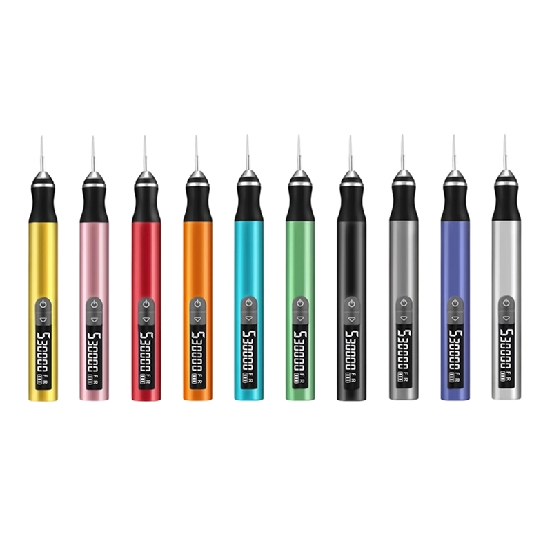
ToolQeen lists plastic carving and model making among the H102's applications. Its 59 g pen body provides a compact handpiece for positioning near a small target. Its 2.35 mm chuck is a fit requirement, not proof that any same-size accessory is suitable. Confirm the accessory's material use, mounting and speed limits before powered work.
Remove supports and test the complete setup
Remove large, accessible support pieces with suitable hand tools before attempting fine finishing. Support the print close to the area being worked so that removing waste does not bend the joint flange. Secure the part in a padded fixture or clamp that prevents movement without distorting the printed walls.
Put on eye protection and arrange dust collection suitable for plastic sanding debris; use respiratory protection as required by the material and accessory guidance. Keep the adhesive, mating half and loose hardware away from the dusty work area. Switch the tool off before mounting or checking the accessory, following its instructions.
Use scrap from the same filament and a similar printed section to check contact behavior. The H102 has five adjustable gears, but a maximum-speed specification does not select a working setting for this joint. If the confirmed accessory cannot remove material cleanly without chatter, smearing or excessive pressure, use a hand method instead.
Make a local correction and repeat the dry fit
Approach only the identified excess with light, brief contact. Keep the surrounding shoulder or flange in view. Stop the tool before brushing away debris or changing the workholding position. The aim is to reduce the obstruction incrementally, not to make the whole area visually uniform in one pass.
PLA requires particular care around frictional heating; a glossy smear or softened edge is a reason to stop, allow cooling and reassess. Do not transfer a successful approach from one filament to an unfamiliar blend. Keep powered work dry unless the exact tool is explicitly approved for another method; hand wet-sanding advice does not authorize wet rotary use.
Clean the contact area and repeat the dry fit. Does the seam close more evenly? Does the piece still locate positively? If the gap moves elsewhere, inspect again instead of following it with the abrasive. Several mismatched features may indicate a printing or design issue rather than several separate burrs.
Prepare for adhesive and later painting
Once the parts seat as intended, follow the adhesive manufacturer's requirements for surface preparation, cleaning, drying and cure conditions. Prusa's guide to gluing and assembling 3D prints explains why material and adhesive choice matter; it does not establish one glue for every printed polymer. Trial the chosen adhesive on spare pieces when compatibility or appearance is uncertain.
Keep polishing compounds, oily handling residue and loose abrasive dust off bonding faces. A smooth-looking surface is not automatically the right surface for adhesion. If the instructions call for abrasion, use the specified preparation rather than an arbitrary deep crosshatch made with the rotary pen.
Check alignment while the joint remains adjustable, then allow the specified cure before any external seam finishing. For painted models, keep the bonding faces free of unapproved coatings. After assembly, treat raised glue residue and recessed seam gaps as separate problems, and test the filler, primer and paint combination on scrap.
Common mistakes and a useful stopping point
One common mistake is polishing every mating surface before discovering how the pieces fit. Another is repeatedly sanding both sides: the source of improvement becomes unclear, and locating features can become loose. Work on one identified defect at a time and preserve an untouched reference wherever possible.
Do not treat extra glue as a reliable cure for poor alignment. Equally, do not pursue a completely invisible dry seam if the design intentionally provides adhesive space. Stop when the parts register correctly, the joint is free of obstructing debris and the adhesive preparation matches its instructions.
For a repeat print, record which face needed correction and whether the cause was support placement, a first-layer lip or a dimensional mismatch. Correcting that cause in the model or print setup can be more useful than repeating the same hand adjustment on every copy.
Frequently Asked Questions
Frequently Asked Questions
Should I rotary-sand both halves until they touch everywhere?
No. First determine whether full contact is intended. Remove identifiable excess, then recheck. Broad face correction is better controlled with a supported hand abrasive, and a designed adhesive gap should remain part of the joint.
Can the H102 make an undersized socket fit a large pin?
It may remove a local entrance burr with a confirmed accessory, but it is not a precision boring system. If the entire socket is undersized, revise the fit or use an appropriate controlled process rather than freehand enlarging it.
Does a pit in the glue face need more sanding?
Usually it needs assessment, not automatic removal of surrounding plastic. A suitable gap-filling adhesive may accommodate it within the adhesive's limits; a deep defect or damaged load-bearing area may justify a reprint.
Can I glue immediately after dry sanding?
Only after removing dust and completing the adhesive's required cleaning and drying steps. Dust left in a joint can obscure the fit and contaminate the bond. Follow the specified handling and cure times.
What should I ask before buying the rotary pen?
Describe the filament, joint shape and smallest accessible target. Ask which H102-compatible accessory is approved for that work and request its mounting and operating instructions. An accessory count alone does not answer those questions.
Final Buyer Recommendation