
Rotary Tool and 3D Print Finishing
Fitting 3D Printed Sliding Joints Without Sanding Them Loose
Fit 3D printed sliding joints by locating interference, preserving guide faces and checking the full travel. Learn where rotary spot cleanup helps without adding play.
Quick Answer
Fit 3D printed sliding joints by locating the specific point of interference before removing material. A mini rotary tool can reduce a visible nub on a robust entry area, but long guide faces and dovetail angles are usually better preserved with controlled hand finishing or a corrected print. Check the full travel, alignment and unwanted play after each adjustment, not just whether the parts can start together.
Buyer Takeaways
- Distinguish an entrance obstruction from binding along the full guide.
- Keep rail faces, dovetail angles and travel stops as designed.
- Adjust one identified feature at a time and clean before each fit check.
- Easy insertion is only useful if the finished joint still guides and retains the part.
Define what a successful sliding joint should do
A sliding box lid should move along its rails without binding, remain supported and reach its intended stop. A removable dovetail display mount may need a different amount of friction. Before sanding, decide what the design intends: free movement, a snug removable fit or a position held by another fastener.
Keep a correct companion part available for checking. A rail finished against an improvised substitute may still fail with the actual lid. Verify the orientation of both parts and whether the design includes an intentional taper, lead-in or end stop.
Do not confuse a tight joint with a strong joint. Excessive force can split a printed rail, while excessive clearance can let the parts rock or disengage. The finishing task is to remove a defect within a sound design, not to find an arbitrary middle point by sanding everything.
Locate the start and extent of the interference
Clean loose strands and support debris from both pieces. Insert the moving part gently until resistance begins, then stop. Note whether the problem is at the entrance, at one position along travel or throughout the guide. Inspect that region with the pieces separated.
A first-layer lip at the entrance is a different target from a rail that is undersized along its entire length. A local support nub may produce one tight spot. A warped lid may bind differently as it enters farther. Those observations should determine the next action.
Compare the guide dimensions and straightness with the design where practical. Formlabs' interlocking-joint guidance emphasizes the relationship between intended clearance and manufacturing variation. It does not establish a single correct gap for every FDM printer, material and rail length, so do not copy a number without evaluating the actual assembly.
Technical Explanation
Preserve guidance as well as clearance
A sliding joint needs clearance, but also needs contact geometry that guides its motion. Local removal can eliminate an isolated obstruction while preserving that geometry. Broad uneven removal can instead tilt the moving part, create play or shift the contact to another region. Ease of motion and accuracy of guidance must therefore be checked together.
Choose a tool that preserves the guide
For a straight rail face, a suitably sized fine file or abrasive on a rigid support can preserve the intended plane more predictably than a rotating point. Keep the support aligned with the face instead of rounding the entrance into a funnel. Dovetail angles need the same deliberate treatment.
A rotary pen may help with a clearly raised nub on a robust, accessible entry feature. It is poorly suited to sweeping a long internal groove to a consistent size. If the accessory cannot reach the defect without touching the opposing face, use a hand method or revise the print.
Do not remove a stop or retaining lip simply because it interrupts movement. Check the design first. Likewise, a recessed gouge is not improved by lowering the entire guide face to match it. That can introduce play across a much larger area.
Prepare the test and workholding
Separate the parts and remove nearby hardware. Support the rigid body close to the target without bending the rails. Before starting, confirm that the clamped part has the same shape it had when free. A bowed rail can seem easier to finish while producing the wrong geometry afterward.
Wear eye protection and manage plastic dust at the work area. Keep the companion part clean so residue does not distort the next fit check. Remove large support remnants with suitable hand tools before abrasive work, and inspect for cracks along the rail roots.
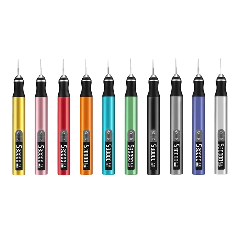
The H102 has a 2.35 mm chuck, five adjustable gears and a digital display. Confirm the proposed accessory's fit, plastic suitability and operating limits, then test on matching scrap. A maximum-speed rating does not specify the right setting for a thin rail or a dovetail entrance.
Correct the obstruction without widening the whole path
Reduce one identified protrusion with a small, controlled action. If using a confirmed rotary accessory, keep contact brief and light, with the adjacent guide face visible. Stop before the working surface begins to reshape the rail itself. Finish the final transition by hand when that gives better boundary control.
Switch the tool off before inspecting, clearing debris or moving the fixture. If the plastic smears, chatters or begins to soften, stop and reassess. PLA needs particular care around frictional heat, and other polymers need their own testing. Do not assume that a lower setting can make an unsuitable accessory geometry safe.
Clean the joint and test again. If entry improves but binding remains farther along, inspect that new contact position. Do not respond by automatically removing material along the full rail. A change in the symptom may reveal a second defect or a larger alignment problem.
Test travel, guidance and retention together
Once the parts engage, move them slowly through the intended range without forcing them. Look for a tight spot, sideways rocking or a tendency to lift out of the guide. Check that the stop still limits travel and that the intended retention feature remains present.
Inspect the surfaces after the trial. Fresh scuffing can help locate contact, but a visibly damaged rail or split layer means the test should stop. Do not continue cycling a weakened assembly in the hope that it will wear itself into a better fit.
For painted parts, account for the final finish before declaring the fit complete. Coating on both opposing faces consumes working clearance. Protect areas that should remain uncoated, follow the finish manufacturer's instructions and repeat the assembly check after curing. Do not apply cosmetic filler to a guiding face as an improvised dimensional repair.
Record the correction and improve the next revision
Keep a short record of where the joint bound, which face you changed and what happened afterward. When adjusting one part of a pair, avoid modifying the other at the same time. Otherwise, it becomes difficult to know whether the improvement came from a small correction or excessive combined clearance.
If all copies bind throughout the same rail, review the design and printing setup. If one copy is warped, a corrected reprint may be better than hand-fitting it to a distorted shape. A small fit coupon can help evaluate the next revision before printing a complete enclosure.
Common mistakes include rounding every entrance, polishing guide faces indiscriminately and judging success only by easy insertion. Stop when the joint performs its intended movement and retention without force, visible damage or unwanted play. Further removal then risks converting a useful fit into a loose one.
Frequently Asked Questions
Frequently Asked Questions
Can I use a rotary pen along the entire dovetail groove?
That is not the approach recommended here. Freehand removal is difficult to keep consistent along angled guide faces. Reserve powered work for an accessible local defect and use a controlled method or revised print for overall sizing.
The lid enters halfway and then stops. Where should I sand?
Do not choose a face until you inspect the contact at that position. Look for a local nub, distortion or a changing guide width. Clean both pieces and compare the design before removing material.
Should both rails be sanded equally?
Only if evidence shows that both require correction. Symmetrical removal is not automatically correct, especially when the defect is local. Change one identified area and recheck so you can understand the result.
Can paint make a previously good sliding fit tight?
Yes, coating buildup can reduce the gap between opposing surfaces. Plan the finish around functional interfaces and check the cured assembly. Do not rely on forcing the parts together to remove excess coating.
What if I have already sanded the joint too loose?
Stop removing material. A cosmetic coating is not a predictable way to restore a guiding surface. Depending on the design, a revised replacement part or an intentional mechanical adjustment may be needed.
Final Buyer Recommendation