
Rotary Tool and 3D Print Finishing
Marking 3D Printed Prototypes with an Electric Engraving Pen
A guide to marking 3D printed prototypes with an engraving pen: choose a safe label area, test shallow marks, preserve functional surfaces and record each revision.
Quick Answer
Marking 3D printed prototypes with an engraving pen can keep similar revisions identifiable after cleanup and repeated handling. Put a short, shallow identifier on a robust, nonfunctional marking area, test the exact filament first, and keep the part securely supported. Use labels or text added before printing when the wall is thin, the appearance must remain untouched or the mark would affect a fit or test surface.
Buyer Takeaways
- Choose the marking location before choosing the lettering style.
- Keep identifiers away from thin walls, stressed roots and precision mating faces.
- Use a short code connected to a separate record of the print settings and revision.
- Validate legibility and surface condition on a matching coupon before marking the part.
Decide what information needs to stay with the part
Several nearly identical prototypes can become difficult to distinguish once supports are removed and the pieces leave the printer. A short revision code on each part can help you match a fit observation to the correct model file. The mark should identify the object, while a separate notebook or file holds the detailed settings.
Choose a simple format that you can read consistently, such as a project abbreviation and revision number. Avoid ambiguous characters when they are likely to be confused. Mark related halves separately if they may be separated during testing, rather than assuming they will always remain together.
An engraved code is an identification aid, not proof of a material grade, certification or test result. Only mark information you can trace to the actual part. If the filament or file revision is uncertain, resolve that uncertainty in the record before adding a permanent claim to the print.
Pick a marking area that does not change the test
A dedicated thick pad or a broad nonfunctional underside is a better candidate than a latch root, hinge knuckle or thin outer wall. Check the model and sliced structure to understand what lies beneath the intended mark. A flat-looking face can still be only a thin shell over infill.
Keep the identifier away from surfaces used to assess fit, flatness, sealing or wear. Engraving removes material and can leave a small raised edge around the stroke. That matters if the face is supposed to slide against another component or sit flush against a reference surface.
For a prototype intended for a mechanical test, do not add a notch in the region being evaluated. Use a tag, a suitable label or a separate marking area that does not influence the measurement. Cosmetic convenience should not change what the prototype is meant to demonstrate.
Technical Explanation
Choose the marking location first
Engraving creates a recess and may leave a small edge around it. On a designated marking pad, that can be acceptable; on a mating, bearing or stressed surface, the same mark can alter behavior. The location and remaining material are therefore more important than a claim that a particular pen is precise enough for every prototype.
Compare engraving with labels and printed text
A removable label works well when the identification changes or the part has no suitable engraving area. Check its compatibility with the surface and intended handling. It should not obstruct a fit or leave residue where bonding will occur. Keep the identifier in the accompanying record as well.
Text modeled or added in the slicer can be preferable for a repeat design. PrusaSlicer's Text tool supports labels and version numbers before printing. Inspect the sliced result to ensure the characters and underlying wall remain suitable. Adding text before printing does not eliminate the need to consider location and legibility.
Engraving is useful when a finished, sound part needs a lasting local identifier and a suitable marking pad already exists. Dremel's beginner guidance supports practicing on manageable surfaces and stabilizing the workpiece; its accessory numbers and tool settings should not be transferred to the H102.
Select a verified setup and prepare a coupon
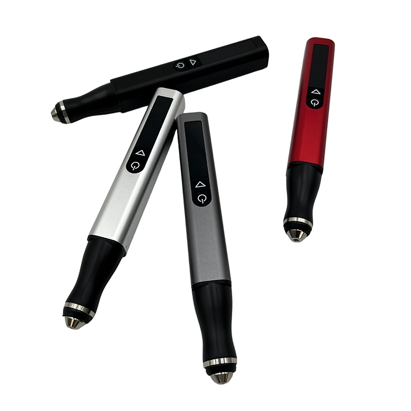
ToolQeen lists plastic carving and model making among the H102's applications. The 59 g pen body and digital speed control are relevant to positioning a small marking tool, but they do not establish an automatic engraving depth or minimum readable character size on FDM plastic.
Confirm the engraving accessory for the filament, intended contact and the H102's 2.35 mm chuck. Check its operating limits and mounting instructions. The public product page lists five adjustable gears and a maximum of 30,000 RPM, but does not publish a filament-specific marking chart or RPM for each gear.
Print a coupon with the same material, surface orientation and adequate solid marking area. Trial the actual code, not just an unrelated scratch. Examine whether strokes cross layer texture cleanly and remain distinct after loose debris is removed. Reject a method that requires force, smears the surface or digs unpredictably.
Mark the supported part after basic cleanup
Remove support waste and complete any local surface cleanup needed to expose the marking pad. Secure the part with padded workholding that prevents movement without deforming the print. Wear eye protection and control plastic dust near the contact point, following the material and accessory guidance for respiratory protection.
With the tool switched off, confirm that the entire intended stroke path is visible and accessible. Arrange the identifier using a layout method that leaves the work area clean and does not introduce loose material near the rotating accessory. Follow the tool manufacturer's handling instructions.
Use the confirmed accessory and a setting established on the representative coupon. Make a light, shallow identifier rather than carving a decorative deep groove. Stop between small portions to inspect after the accessory has stopped. If the tool wanders, catches or produces a smeared edge, stop and reassess instead of cutting deeper to correct the line.
Inspect the identifier before returning to assembly
Allow any warming to dissipate, remove loose residue and read the code under normal working light. Check it from the usual viewing angle. A mark that is visible only under an extreme reflection may not serve its purpose, but increasing depth is not the only way to improve identification.
Inspect the surrounding plastic for cracking, a gouge, exposed infill or distortion. Keep the part out of service if marking has damaged a functional area. PLA can soften under frictional heat, and other formulations require their own evaluation. Do not improvise solvent or flame treatment to make a poor mark look cleaner.
If the part will be painted, test whether the planned coating preserves legibility and whether a different identifier method is more appropriate. Follow the coating instructions, protect assembly surfaces and check the final code after curing. Record where the mark was placed and link it to the correct revision entry.
Make identification part of the next design
For future prototypes, add a deliberate marking pad or readable printed revision field in a suitable area. Keep it separate from functional interfaces. This reduces the temptation to engrave whichever surface happens to be reachable after the part is assembled.
Record the model revision, filament identity, relevant print settings and any manual finishing changes under the same code. If one trial part has been hand-fitted more than another, that difference belongs in the record. Otherwise, a fit comparison may be attributed to the CAD revision when it actually came from cleanup.
Common mistakes include deepening unclear strokes repeatedly, marking over an old code without resolving the record, and placing IDs on stressed features. Stop when the identifier is unambiguous, the print is undamaged and the record correctly describes the object. Decorative perfection is not required for useful traceability.
Frequently Asked Questions
Frequently Asked Questions
How deep should an identifier be engraved?
There is no universal depth for FDM prints. Use the shallowest suitable mark demonstrated on a representative coupon and supported by the accessory instructions. If legibility requires substantial removal, choose another identification method or redesign the marking area.
Can I mark a thin enclosure wall with the H102?
Do not assume it has enough material. Check the model and sliced wall structure first. When the remaining thickness or functional effect is uncertain, use a compatible label or a separate tag instead.
Should I mark the part before or after sanding?
Complete cleanup that would otherwise remove or obscure the identifier, then mark a suitable clean area. Plan later paint and assembly steps so the code remains readable. Avoid abrasive work around installed electronics or loose hardware.
Can the same setting be used on PLA and PETG?
Not without separate confirmation and testing. The exact formulation, accessory and printed surface matter. Five adjustable gears are a control feature, not a validated recipe for every polymer or character size.
Is engraving better than adding the revision in the slicer?
It depends on when the ID becomes known and whether the part has a safe marking area. Slicer text is useful for planned repeated revisions; engraving can identify an already printed sound part. Labels suit surfaces that should remain unaltered.
Final Buyer Recommendation