
Rotary Tool and 3D Print Finishing
FDM Layer Lines: What a Mini Rotary Tool Can and Cannot Fix
Understand FDM layer lines, isolated support scars and recessed defects. Choose rotary spot cleanup, supported sanding or compatible filler for the surface.
Quick Answer
FDM layer lines are repeated surface geometry, while a support nub is a local protrusion and a pit is missing material. A mini rotary tool can help with selected raised defects on robust areas, but it does not guarantee complete layer-line removal. Broad surfaces usually need supported hand preparation, and cosmetic low spots may need compatible filler.
Buyer Takeaways
- Identify repeated layer texture separately from support scars.
- Preserve wall thickness and fine relief while improving appearance.
- Do not confuse a changed sheen with a corrected surface.
- Plan sanding, filling and coating as distinct operations.
Decide what the visible lines actually are
Under side lighting, a print can show horizontal texture, a vertical seam, isolated support contacts and scratches from earlier cleanup. They may all look like “lines,” but they do not share one remedy. Compare the surface with the model, its orientation and an untouched part before selecting a finishing method.
Repeated FDM layer texture follows the deposited geometry. A raised support nub stands above a local surface. A recessed scar sits below it. A crack or separated layer is a structural concern rather than ordinary cosmetic texture. Identifying these features prevents a small tool from being used to grind every visible mark indiscriminately.
Set a finish target appropriate to the part. A display panel intended for paint may need a different surface from a functional bracket or textured terrain model. A uniform gloss is not necessarily useful, and a smooth appearance does not prove the print remains dimensionally correct or mechanically sound.
Understand the material budget of smoothing
Removing surface peaks takes away part of the printed wall. If you keep removing material until the deepest valley disappears, the outside dimension and remaining shell may change substantially. A decorative curve can become flat, an embossed letter can lose height and a thin wall can expose infill.
Inspect the model's construction before planning broad removal. Check which areas are solid, which are shells and which must mate with another part. Do not assume that a large object has thick outer walls. The margin for cleanup comes from its geometry, not its overall size.
This is why a local support nub and an entire field of layer texture deserve different methods. The nub may be reduced without substantially changing the surrounding wall. Smoothing a whole face requires a plan for preserving that face and deciding whether material should be removed, added or left visible.
Technical Explanation
What changes during cleanup
Abrasive removal cannot add material to valleys or pits. Eliminating every visible low point by lowering the surrounding surface spends wall thickness and changes dimensions. Use the model's required geometry to decide how much removal is acceptable and where a compatible cosmetic addition is more appropriate.
Give the rotary tool a small, defined job
An accessible raised support remnant on a substantial wall may suit a documented rotary accessory. Remove large supports first with suitable hand tools, wearing eye protection and avoiding leverage against thin features. Leave a stubborn small nub rather than tearing out the surface beneath it.
Secure the cooled print in padded support and arrange appropriate extraction for plastic dust. Check access with the tool off, keeping the chuck and unused head surfaces clear of the model. Inspect mounting, condition, shank fit, material suitability and speed limits with power off and charging disconnected.
Trial the setup on representative scrap from the same filament. Use brief, light contact at an allowed setting and inspect with the tool stopped. If the result preserves the contour, reduce the specific nub on the model and finish the last trace by hand. Do not continue across the whole face merely because the tool is already running.
Use hand preparation to preserve a broad surface
For a planar panel, support abrasive paper on a flat block and inspect the whole face rather than one shiny patch. For a gentle curve, use an appropriate backing and method that preserve the intended form. Loose paper wrapped around a fingertip can soften corners while leaving other areas nearly untouched.
Choose abrasive grades according to their maker's guidance and a trial result. Start with the least aggressive option that does the required work. Refine the scratch pattern only as needed for the planned finish; following a long grit sequence automatically can consume material without improving the intended result.
Stop frequently to clean and inspect. PLA can be damaged by frictional heat, while PETG and other grades require separate evaluation. Any material-supported wet hand process should be kept separate from the electric pen. Thin relief, sharp design boundaries and mating surfaces may need protection from both abrasive removal and later coating buildup.
Fill low spots when the cosmetic goal requires it
For a sound display part, adding compatible filler can sometimes address a low area without lowering the surrounding wall. Select the filler with the filament and final coating in mind. Follow its preparation, protection and curing instructions, then test the complete finishing system on spare material.
Use the prescribed hand-finishing approach on a cured repair and inspect the boundary. Plastic and filler may abrade differently. A remaining hard patch is not a reason to keep removing softer surrounding material until a trough appears. Check shape with side lighting and from several angles.
Prusa's postprocessing walkthrough shows how filling, sanding and painting can form separate stages of a model finish. It does not establish that every filler should be machined with a rotary pen. Keep added materials within their own instructions. A filled cosmetic surface also does not repair split layers or prove that a weakened wall is fit for use.
Separate polishing from geometric correction
Polishing concerns surface finish under the requirements of the material, wheel and compound. It should not be presented as a guaranteed shortcut for erasing the printed geometry. A surface can become shinier while layer texture remains, and concentrated friction can create a new problem instead of a smoother model.
Do not assume that a polishing head shown in a kit is appropriate for PLA, PETG, paint or cured filler. Confirm the entire combination, including compound and permitted speed, before considering that operation. If the information is absent, use a supported finishing method rather than transferring another brand's procedure.
Before paint, inspect the cleaned surface and follow the coating's preparation instructions. Primer may reveal small defects that were difficult to see in bare plastic, but it does not promise to hide every layer or bridge a deep scar. Preserve intentional detail and check fit before and after the relevant coating stages.
Choose the H102 for local cleanup, with clear limits
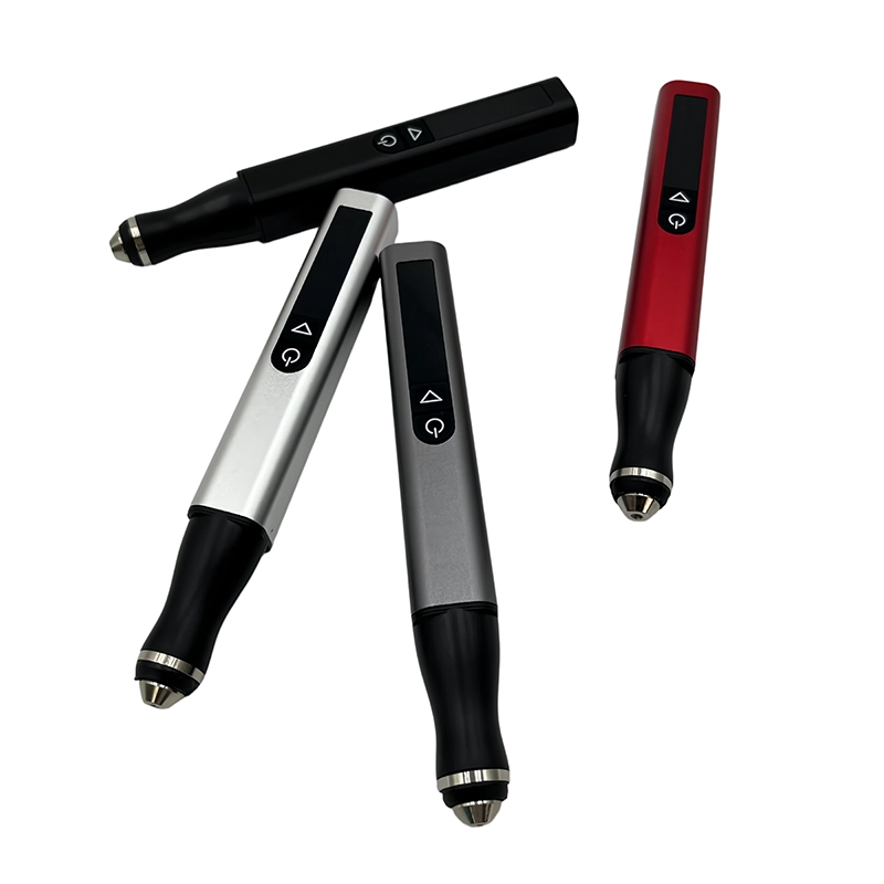
ToolQeen's H102 listing includes plastic carving and model making. The pen-shaped 59 g body can help position an accessory beside an isolated raised mark. Five adjustable gears and a digital display make an approved setting identifiable for repeat trials; they do not guarantee a layer-free surface.
The listed chuck is 2.35 mm and the configuration includes 30 accessories. The page does not publish every grit, a polishing-compound system or a filament-specific operating chart. Ask about the exact plastic-compatible head and its instructions rather than assuming all of the accessories suit the same model-making task.
The listed maximum speed is 30,000 RPM, while the minimum and individual gear values are unspecified. Treat this as product information, not a smoothing recipe. Confirm the supported combination and single-unit or sample availability through ToolQeen's inquiry route. Select the pen for a defined local job within a broader finishing plan.
Frequently Asked Questions
Frequently Asked Questions
Can a mini rotary tool completely remove FDM layer lines?
There is no universal guarantee. The result depends on geometry, wall thickness, material and the supported accessory setup. Broad layer texture is usually better approached through planned hand preparation and, where appropriate, a compatible filling and coating system.
Why are layer lines more visible after the surface becomes shiny?
A changed sheen can make existing geometry catch light differently. Inspect the surface shape rather than assuming shine equals smoothness. Do not respond by increasing powered contact without identifying what still needs correction.
Should I sand down to the deepest support pit?
Usually that would remove sound material unnecessarily. Assess compatible cosmetic filler for a sound display part. If the pit weakens a wall or exposes infill, consider replacement rather than a purely surface-level repair.
Will filler primer preserve tiny lettering?
That depends on the product, application and detail. Coating buildup can obscure shallow relief. Follow the primer instructions and test on a representative spare before applying it to fine features that must remain legible.
What can I change before the next print?
Review orientation, layer settings and support placement in the printer and slicer documentation. A small representative trial can show whether the visible face improves. Better print preparation may reduce the amount of material removal needed later.
Final Buyer Recommendation