
Rotary Tool and 3D Print Finishing
Cleaning 3D Printed Hinges: A Careful Guide to Free Movement
Clean 3D printed hinges by separating surface burrs from fused gaps and alignment errors. Learn where local rotary cleanup helps and where hand tools are safer.
Quick Answer
Cleaning 3D printed hinges begins by deciding whether resistance comes from a visible burr, a misaligned pin path or a fused printed gap. A mini rotary tool can help remove accessible excess from a robust, disassembled hinge end face. It should not be pushed into a captive joint or used as a freehand reamer. Clean, reassemble and test movement after each small correction.
Buyer Takeaways
- Separate removable-pin hinges from mechanisms printed as a captive assembly.
- Preserve pin alignment, bearing surfaces and the material around each knuckle.
- Diagnose the point of resistance before removing plastic.
- Stop when the required movement is free without introducing unwanted looseness.
Identify the hinge construction before touching it
A box with separately printed hinge leaves and a removable pin can often be inspected piece by piece. A print-in-place chain or articulated model may have inaccessible internal gaps. The finishing options are not interchangeable. Do not force a rotating accessory into a trapped joint simply because its tip appears small enough.
Check whether the pin is intended to rotate, remain fixed or be retained by a separate feature. Look for any planned stops that limit travel. What seems like a rough edge may actually be the surface that prevents the lid from opening farther.
This guide covers small rigid FDM hobby assemblies, not hinges whose failure could injure someone. For the ordinary model in front of you, the goal is modest: remove a clearly identified printing defect while keeping the intended geometry and movement.
Distinguish rubbing, misalignment and fused material
On a removable-pin design, inspect the leaves independently and check that the correct pin is being used. Compare its dimensions with the design rather than relying only on a nominal hardware size. A pin that will not enter one leaf separately points to a different problem from leaves that fit separately but bind together.
If the assembled hinge stops at one angle, look for an external collision or a local support nub. If resistance is continuous, consider alignment, bearing clearance or overall dimensional error. Debris between end faces can also produce misleading resistance, so clean before judging.
For a print-in-place hinge, a visible external strand may be removable with a suitable hand tool. A fully fused internal gap is not an invitation to drill or grind blindly. Follow the model designer's release instructions; when access is inadequate, correct the print and reprint the part.
Technical Explanation
Keep the intended hinge axis
A hinge has an intended axis of rotation. Debris or a burr may obstruct motion without moving that axis, while uneven removal from holes or seating faces can change alignment. Making the joint easier to move by adding clearance everywhere may therefore hide the original problem and introduce wobble. Diagnose before reducing material.
Match the finishing method to the contact surface
A fine file is useful on a straight, accessible end-face burr because you can keep the neighboring face in view. A narrow supported abrasive can address a local rough patch. A round-looking tool is not automatically suitable for a bearing hole: a changing bore diameter can leave the pin loose at one end and tight at the other.
Reserve rotary cleanup for visible excess on a robust exterior or end face with a clear approach and exit. Do not remove a full ring of material from every knuckle as a routine finishing step. Each face contributes to the assembly's spacing and alignment.
Formlabs' guide to interlocking assemblies explains why clearance and manufacturing variation must be considered together. Its process-specific dimensions are not a prescription for your FDM hinge. Use the actual design and measured parts, then decide whether the problem is a burr or a fit that needs revision.
Set up for stable contact away from the joint
Remove the pin and separate the leaves when the design allows. Clamp the rigid leaf body with padding and support near the target, without crushing the knuckles. Keep the removed pin away from the abrasive area so dust does not become trapped in the joint during the next trial.
Wear eye protection and collect dust where it is produced, following the filament and accessory guidance for respiratory protection. Remove large support pieces with appropriate hand tools first. Stop if that removal exposes a crack at the base of a knuckle; surface finishing will not restore its strength.
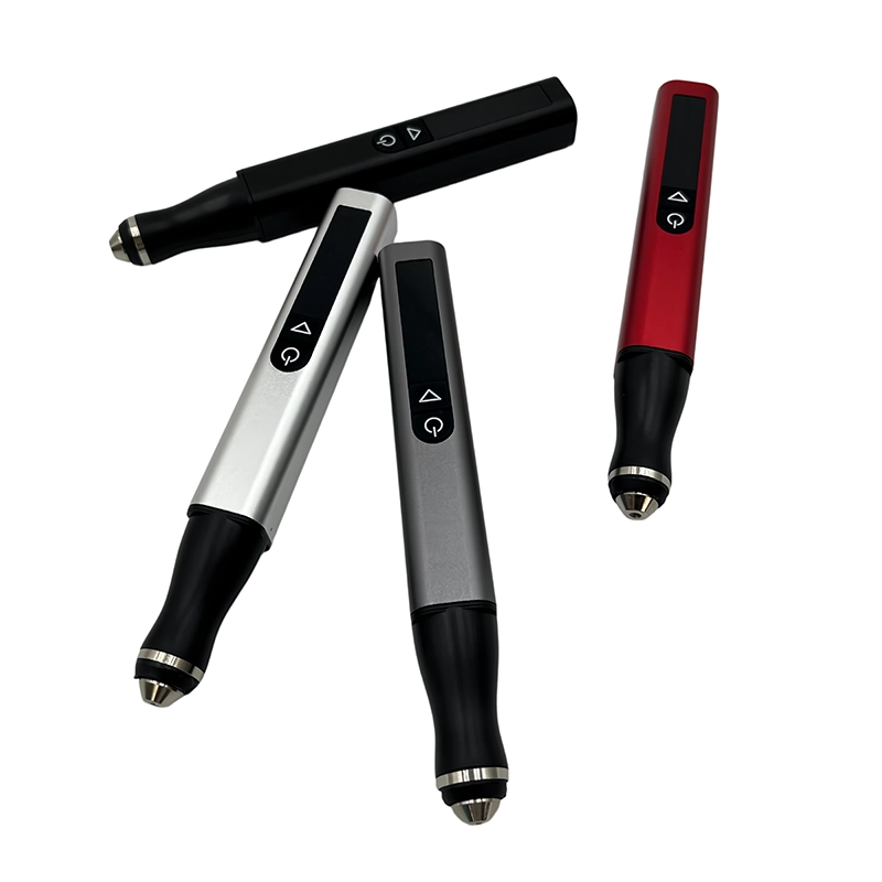
ToolQeen's H102 has a compact 59 g body and a 2.35 mm chuck. Check the selected accessory's mounting, material suitability and permitted operation. Test on matching scrap before touching a finished leaf. The published maximum speed is not a recommended hinge-cleanup speed, and an unverified extension should not be added for reach.
Remove a small defect without changing the axis
Mark the location mentally or in a work note, then address only that raised material. A confirmed rotary setup should work with light, brief contact; if you need to lean hard on the tool, stop and change the method. Keep both the defect and the protected adjacent face visible.
Avoid chasing a smooth appearance around the full circumference of a knuckle. Uneven freehand removal can change its seating and create a new source of play. Finish the last small transition by hand if that offers a clearer contact boundary.
Switch off before checking the surface or clearing dust. Pause at any sign of melting, smearing or chatter. PLA is particularly vulnerable to frictional heat, but a different polymer is not permission for longer contact. Powered work remains dry unless the exact tool is explicitly approved for another method.
Reassemble and inspect motion in stages
Clean the leaves and pin, then assemble without forcing alignment. Check movement gradually through the intended range. Note whether the original resistance is reduced, unchanged or moved to another position. A change in the symptom is useful diagnostic information; it is not automatically a reason for more grinding.
Check for unwanted side movement as well as easy rotation. A lid that swings freely but wobbles at the hinge may have lost useful support. Confirm that the pin remains retained as intended and that mechanical stops still work.
If the model will be painted, plan to keep coating buildup out of functional gaps and bearing areas unless the design accommodates it. Let the specified coatings cure and repeat the movement check before final assembly. Do not use filler to hide a crack or rebuild a bearing surface without a suitable validated repair method.
Turn recurring problems into a better next print
If every knuckle needs the same correction, revisit the model dimensions and print setup. If only supported downward faces are rough, consider orientation and support placement. If a first-layer flare is responsible, address that print condition rather than permanently altering every hinge opening by hand.
Keep a short record: part revision, filament, location of excess, finishing method and final movement. This lets you distinguish an isolated cleanup success from a systematic fit problem. It also avoids mistaking a loose prototype for proof that a hinge design is correct.
Common mistakes include sanding while the hinge is assembled, using the pin as a guide for a rotating cutter, and removing travel stops because they interrupt motion. Stop when the intended range is available, the pin remains aligned and retained, and the surrounding print shows no damage.
Frequently Asked Questions
Frequently Asked Questions
Can the H102 enlarge a printed hinge hole?
This guide does not recommend freehand rotary boring or reaming. The H102's chuck dimension is not a guarantee of bore accuracy. Correct the design or use a suitable controlled sizing method when the whole hole is undersized.
What should I do with a fused print-in-place hinge?
Follow the designer's release instructions and inspect the accessible area. Do not force a spinning accessory into a hidden gap. If the intended clearance did not print, revising the setup and reprinting is often the sounder choice.
Should I remove all layer lines from the knuckles?
No. Target interference that you can identify. Removing layer lines everywhere changes geometry and may add play without improving the actual obstruction. A functional hinge need not have a polished cosmetic surface.
Can lubricant replace cleanup?
It does not remove a burr, fix misalignment or restore a cracked knuckle. Only consider a lubricant compatible with the material and intended use after the geometry and cleanliness are correct, following its supplier's guidance.
Why does the hinge bind only after painting?
Coating buildup or trapped residue may have changed its working clearance. Inspect without forcing it. On the next finish cycle, plan protected functional areas and account for any required coating thickness before assembly.
Final Buyer Recommendation