
Electric Rotary Tool
Finishing Translucent 3D Prints: Edges, Haze and Light
Finishing translucent 3D prints means judging light as well as touch. Clean accessible edges, protect thin walls and avoid promising clear optics from rotary polishing.
Quick Answer
Finishing translucent 3D prints requires checking how they look in transmitted light as well as how the surface feels. Remove a genuine raised edge defect only where the wall can tolerate it, and test the appearance on matching scrap. A mini rotary tool can assist local edge cleanup, but it cannot promise optical clarity or remove internal layer boundaries and voids.
Buyer Takeaways
- Separate the light-transmitting face from the edge or mounting area you need to clean.
- Test the result against the same background and lighting before changing the final part.
- A smoother surface may still look hazy, uneven or visibly different from the untouched plastic.
- Preserve wall thickness and assembly fit instead of trying to polish the entire print clear.
Define the intended appearance before sanding
A translucent decorative insert, a frosted-looking display panel and a clear viewing window have different goals. Decide whether the piece should transmit an image, soften the view behind it or simply let color and light through. This guide focuses on decorative FDM parts, especially unfilled translucent PETG. It does not validate optical components, protective lenses or a lamp's electrical and thermal design.
Examine the cooled print against a consistent background and light source. Note the areas that are acceptably uniform, the edges that carry support remnants and the regions that look cloudy inside. Prusa's filament-transparency discussion explains that material and printed thickness influence transmitted light. That helps explain why local cleanup can change appearance, but it does not provide a rotary-polishing recipe or show that every transparent filament can become a clear window.
Distinguish surface roughness from internal haze
Run angled light across the outside while also looking through the part. A protruding nub or scratch is a surface feature. Visible infill, internal gaps and layer interfaces lie within the print. Removing material from the outside does not simply erase those internal features. If you cannot locate the source of the appearance problem, test a spare piece before committing the final model to an abrasive sequence.
Also distinguish a depression from a raised defect. Grinding the panel around a pit to make it level can create a locally thinner area with a different appearance in transmitted light. Ordinary opaque model filler may hide a pit but defeat the purpose of the translucent piece. A filled or coated repair requires a material system appropriate to both the substrate and the intended visual effect; no generic filler or clear coating is prescribed here.
Technical Explanation
Surface smoothness and optical appearance differ
Transmitted light is affected by both the surface and the path through the printed material. Abrasion changes the surface and can change local thickness, while internal features may remain. That is why judging only surface smoothness can produce a misleading result. The recommended comparison is visual and practical, not an optical measurement or a claimed ToolQeen transparency test. No haze percentage or clarity improvement is promised.
Keep functional edges and viewing faces separate
A robust mounting tab or concealed rim may allow limited local cleanup without touching the light-transmitting face. Inspect the entire wall around that area and compare it with the design. A thin vase-like shell, narrow snap feature or fragile transparent lip may offer no useful removal allowance. Removing a snag from an edge is a different task from flattening the whole panel.
If a broad face truly needs a controlled surface treatment, hand abrasives with appropriate support can offer more uniform contact than a small rotary spot. They can still change haze and surface texture, so test first. Avoid choosing a polishing wheel simply because the word polishing appears on the tool page. Tool, attachment, compound and plastic all need an established compatible process before you rely on that combination.
Test both the contact and the lighting result
Use a spare print from the same material, with a similar thickness and surface structure. Separate test areas so you can compare an untouched region with each proposed treatment. Keep the background, viewing distance and illumination consistent. Judge the result after debris is removed and the piece is dry, rather than while dust or moisture temporarily changes the surface appearance.
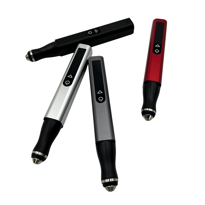
For a suitable edge-cleanup test, the H102's pen body can help place a confirmed plastic-compatible attachment on an exposed protrusion. Check mounting and speed instructions, including the 2.35 mm chuck interface. The five adjustable gears do not establish a translucent-PETG polishing speed. Use the supported setup and brief, light contact. Stop if the surface smears, the edge rounds beyond its intended form or the treated area becomes visually unacceptable.
Secure the part without marking the viewing area
Choose a strong holding region away from the visual face. Clean the fixture contact surfaces, because trapped grit can scratch a translucent part before the finishing tool touches it. Use suitable contained jaw protection where appropriate and check for flexing. Do not clamp a thin panel flatter than its natural shape and then judge it while restrained. Release it for final visual and dimensional inspection.
Wear eye protection and control sanding dust according to the material guidance. Keep the surrounding face free from loose debris while repositioning so it is not rubbed against the bench. Stop the tool fully before clearing dust or adjusting the part. Keep this powered operation dry. Wet hand-sanding advice for a polymer is not permission to use the H102 with water or to improvise a wet polishing setup.
Remove the edge defect and stop at the design
Work only on the identified excess. If the target is a small nub on a hidden rigid tab, the endpoint is a tab with its intended shape and clearance, not a glossy surface. Stop frequently to inspect the adjacent face for accidental contact. Finish the transition by a suitable hand method when that gives better control. Do not chase a small dull patch across the whole panel with the rotary tool.
After cleaning, check both assembly and appearance. The insert should sit without being forced or stressed, and any clip or rim should retain its intended geometry. Evaluate the treated edge in the lighting used by the finished display. If the cosmetic change is worse than the original nub, assess whether a revised print or a tested full-surface treatment makes more sense than another local pass.
Choose a new print when the problem is internal
If the main issue is visible infill, internal gaps or uneven printed thickness, return to the model and printing process. Follow the filament and printer guidance for the intended visual result, and use representative tests. Do not copy another person's transparency settings without considering the actual material and geometry. This guide does not supply a universal flow, temperature or layer-height recipe.
For a decorative light-transmitting part, accept that translucency may be the useful result. A piece can look attractive without becoming optically clear. If painting, coating or bonding is planned, test the full material system and preserve functional edges. Never assume that a transparent coating will repair lost dimensions or make a printed part suitable for a heat source. Finishing appearance and suitability for the final installation require separate checks.
Frequently Asked Questions
Frequently Asked Questions
Can the H102 make a clear PETG print look like glass?
No such result is established. Internal print structure can remain visible after exterior finishing. Use the tool only for a confirmed local task and assess any optical treatment separately on a representative test piece.
Why does the sanded area look different although it feels smoother?
The treatment changed the surface texture and may have changed local thickness. Clean and dry the part, then compare it under consistent lighting. Smoothness by touch is not a complete measure of visual uniformity.
Should I polish the entire face to match one cleaned edge?
Not automatically. That broadens the job and can remove more wall material. Test a suitable complete process first, or keep cleanup confined to a concealed edge when the design allows.
Can ordinary model filler repair a translucent pit?
It may produce an opaque patch or a different visual effect. Use only a material system suited to the substrate and intended appearance, and test it. Reprinting may be preferable where an unobtrusive repair cannot be established.
Is this procedure suitable for lamp shades or protective lenses?
It does not validate those uses. A lamp component needs appropriate thermal and electrical design, and a protective lens needs its own performance requirements. Decorative finishing guidance cannot establish those properties.
Final Buyer Recommendation