
Electric Rotary Tool
Finishing 3D Printed Gears: Where a Rotary Pen Can Help
Finishing 3D printed gears means protecting tooth shape and alignment. Learn where local rotary cleanup can help, how to inspect rubbing and when a gear needs reprinting.
Quick Answer
Finishing 3D printed gears is mainly about preserving the intended teeth, bore and alignment while removing genuine print debris. A mini rotary tool can sometimes trim an isolated raised spot on an accessible, solid side face. It should not be used to reshape tooth flanks by eye. Clean the gear, inspect the mechanism and check gentle hand rotation before considering powered operation.
Buyer Takeaways
- Identify whether rubbing comes from a side face, tooth mesh or shaft alignment.
- Keep tooth flanks, roots, bearing seats and designed clearances out of an improvised rotary repair.
- Judge a finished gear by its whole rotation, not one smooth position.
- Surface cleanup cannot establish the load capacity or service life of a printed gear.
Begin with an unpowered mechanism
Disconnect power and remove the gear from the mechanism where practical. This workflow is for small hobby demonstration models, especially hand-driven assemblies. It is not a repair procedure for a high-speed drive, lifting mechanism or other part whose failure could cause injury. Follow the mechanism designer's material, assembly and inspection requirements before making any changes.
Collect loose strings and dust and identify the intended surfaces. The tooth sides transmit motion; the bore locates the gear; shoulders and side faces may control spacing. A support nub on a nonfunctional outer face is different from a ridge on a tooth flank. Label the assembly orientation on a separate note or photograph so that later fit checks compare the same arrangement. Keep washers and spacers in their intended order.
Locate the rubbing before removing material
Turn the unpowered assembly gently by hand, if the design allows. Stop at binding and inspect without forcing it through. A gear that rubs an adjacent housing may have a raised side-face defect, but it may also be tilted on its shaft or missing a spacer. Resistance that changes over a revolution can indicate alignment or shape errors. Do not assume every tight point is a high spot that should be ground away.
Inspect the standalone gear against the original model. Look for cracked teeth, separated layers, a distorted bore and ragged root areas. A raised remnant is extra material above the intended surface; a chipped tooth or pit is missing material. Sanding cannot rebuild it. If a tooth has already lost its profile, reprinting is usually the appropriate next step for a hobby part rather than trying to blend the damage into the neighboring teeth.
Technical Explanation
Preserve the complete gear relationship
Gear cleanup should preserve the relationships between tooth shape, axis position and side spacing. A rotary pen offers local material removal; it does not measure or restore those relationships. The guidance here applies the general distinction between a surface defect and a dimensional feature to an accessible hobby gear. No H102 gear-mesh, wear or load test is claimed, and the procedure cannot validate a safety-critical mechanism.
Where local rotary cleanup can be useful
The most defensible task is a small, visible protrusion on a robust side face, away from a working tooth or locating shoulder. There must be room for the entire attachment and chuck, not just the tip. The goal is to remove that excess while leaving the surrounding plane and gear thickness intact. A broad flat side face often favors a hand sanding block because it distributes contact across a controlled plane.
Avoid using the H102 to open a bore, relieve every tooth root or polish all tooth flanks. Those operations change geometry that governs the mesh. A fine hand file also requires care and does not automatically make a dimensional correction valid. If there is no clearly isolated defect outside the critical surfaces, set the abrasive aside and check printing accuracy, shaft spacing and the design instead.
Set up a stable, visible contact
Hold the removed gear securely by a suitable robust area without squeezing the teeth. Protect finished surfaces with clean, contained jaw protection if appropriate. Check that the disk remains flat when held; excessive clamp force can distort it. Eye protection and material-appropriate dust control belong in the setup. Keep debris away from bearings and motor components, and never work on a gear while the mechanism is moving.
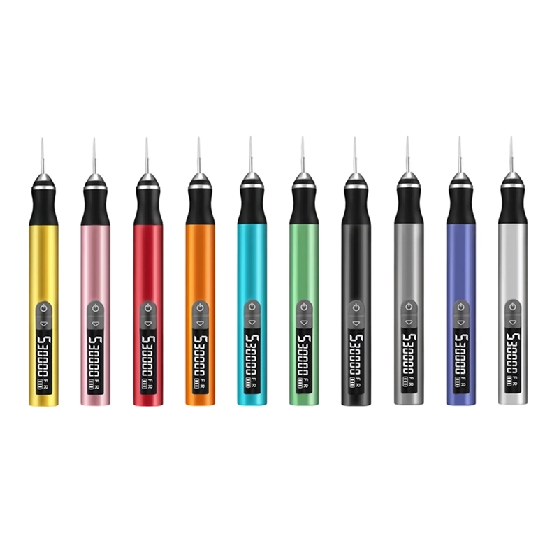
For a confirmed plastic-suitable attachment, the H102's pen format can assist precise placement on the selected side-face spot. Its digital control offers five adjustable gears, but the available product information does not specify a gear-finishing RPM. Confirm attachment compatibility, including the 2.35 mm chuck interface and speed rating, and use matching scrap first. Stop between brief contacts to inspect. Smearing or a widening depression means the process is removing more than the unwanted remnant.
Respect material and tooth thickness
A PLA gear used in a slow hand-cranked model does not establish PLA suitability for a motor-driven gearbox. Material, temperature, duty and tooth geometry all matter. Prusa's RC-model guidance illustrates how different parts call for different materials; it is not a blanket endorsement of one filament for every gear. This article does not transfer those examples into a load rating or speed limit for your print.
Thin tooth tips are vulnerable to accidental contact even when the main disk is thick. PETG, ABS and ASA also respond differently during printing and abrasion. A carbon-filled or glass-filled material requires its own dust and accessory guidance, so do not treat it as ordinary unfilled plastic. No maximum tool speed can serve as a universal finishing setting. If the attachment cannot stay clear of the teeth, use another method or leave the cosmetic blemish alone.
Inspect the gear after releasing the fixture
Stop the tool completely and remove the gear from the clamp. Collect dust, then examine the cleaned area under angled light. Check that a protrusion has not become a hollow or a rounded edge. Inspect the bore and teeth for stray abrasive contact. A scratch across a working surface may be more consequential than the original harmless nub on a side face.
Reassemble according to the design with clean components. Check hand movement through a full revolution and through the intended mechanism travel. Inspect both binding and unwanted play. An easier turn can result from removing too much material, so ease of movement alone is not success. Use only a lubricant specified as suitable for the material and mechanism; adding an unverified lubricant to conceal roughness is not a geometry check.
Keep cosmetic finishing separate from mechanism tuning
For a display model, stop when the intended surfaces are clean and the mechanism moves as designed. Polishing every visible layer line can reduce disk thickness and blur edges without improving function. Paint is another dimensional change: keep it off teeth, locating bores and bearing surfaces unless the design accounts for a coating there. Do any decorative finishing after the mechanical fit has been evaluated.
When several gears show the same error, inspect the print process and model before repeating hand correction on each one. A revised orientation or appropriate fit adjustment may be more useful than a longer finishing session. Keep a note of the actual defect and the area changed. This creates a meaningful basis for comparing the next print instead of attributing every improvement to the tool.
Frequently Asked Questions
Frequently Asked Questions
Can I smooth all the teeth with a rotary polishing wheel?
Do not assume a wheel will preserve the tooth profile. Its contact can round edges or remove material unevenly. Use the designer's specified finishing method for working teeth; this guide limits powered cleanup to suitable isolated areas away from them.
Why does the gear bind once per turn?
Possible causes include distortion, alignment problems and a localized defect. Inspect the assembly and gear rather than choosing one cause from the symptom alone. Forcing it through the tight point may damage the teeth.
Can I enlarge a tight printed bore with the H102?
Freehand rotary enlargement is not a controlled way to maintain a round, centered locating bore. Check the intended fit and use an appropriate specified process or reprint with corrected dimensions instead.
Does smoother plastic mean a stronger gear?
No. Surface appearance does not determine layer bonding, tooth strength, material suitability or operating temperature. Finishing can also weaken a part if it removes important geometry. Treat strength as a design and validation question.
Is a gear with a chipped tooth still usable for a display?
A static display and a working mechanism have different requirements. For a moving assembly, replace the damaged gear rather than blending away the chip. For a purely decorative part, assess its appearance without presenting the result as mechanically repaired.
Final Buyer Recommendation