
Electric Rotary Tool
Cleaning Panel Lines on 3D Prints Without Widening Them
A guide to cleaning panel lines on 3D prints: distinguish blocked grooves from shallow geometry, protect corners and use a rotary pen only where access allows.
Quick Answer
Cleaning panel lines on 3D prints means preserving the width, depth and corners of a recessed detail while removing genuine obstructions. Start with loose debris and inspect the groove under angled light. Use a hand tool where access is narrow. A mini rotary tool is only a candidate for a visible, isolated raised defect on a robust surrounding area, not for blindly tracing every line.
Buyer Takeaways
- A blocked groove and a groove that printed too shallow need different solutions.
- The attachment's whole shape must clear both sides of the recess.
- Protect intersections and corners, where an abrasive can quickly change the design.
- Check details before primer and between coating stages instead of repairing them after heavy paint buildup.
Decide what the line should look like
Panel lines on a vehicle model or science-fiction prop may represent a gap, a joint or a decorative recess. Their job is visual, but their proportions still matter. Before touching the print, compare it with the model file or a clear rendering. Identify the intended start, end, width and corner shape. Layer texture inside the groove is not automatically an obstruction that must be removed.
This guide concerns recessed details in rigid FDM prints. It does not prescribe resin-print cleaning or a powered engraving procedure. A narrow line on a thin shell offers very little room for correction. If the feature is missing because it is below the printing process's useful resolution, carving along an assumed path can create a new, uneven detail rather than recover the design. Revise the model or print setup when that is the real problem.
Reveal the obstruction before cutting it
Remove large supports elsewhere first, supporting the model so they cannot tear through a detailed panel. Clear loose dust from the recess using an appropriate gentle method. Inspect with a small light from more than one direction. A shadow can make a shallow groove appear deeper, while a glossy ridge can look like a gap. Magnification can help distinguish connected surface material from detached debris.
Classify what remains. A small bridge of unwanted plastic across a line is raised material. A pit beside the groove is missing material. A uniformly shallow line is a geometry or printing issue. Each calls for a different response. Do not sand the whole panel down until a pit disappears; that can lower the panel around every other detail. For suitable cosmetic pits, plan filling separately and keep filler from packing the recess.
Technical Explanation
Two edges define the recessed line
A recessed line is bounded by two edges, so removing material from either edge changes its apparent width. A pointed attachment also changes contact width as it moves deeper. These geometric relationships are why a pen-like grip alone cannot guarantee detail preservation. The practical objective is a readable, consistent design after the intended finish, not maximum material removal or a perfectly polished recess.
Select the method by groove shape
A broad open recess with a solid base can be inspected and approached more easily than a deep slot with narrow walls. An appropriately shaped hand file or small supported abrasive can offer controlled access, provided it fits without scraping both edges. Use the tool's intended working surface and keep its path visible. A flat sanding block is better for a broad adjacent panel than for reaching the bottom of a line.
Avoid choosing a rotary point merely because its tip fits the opening. The taper behind the tip may touch the sidewalls, and the chuck can obstruct the view. Intersections, tight radii and blind ends are especially easy to widen accidentally. A line that cannot accommodate an attachment with clearance is not a rotary-cleanup candidate. Leave the texture, use an appropriate hand method or improve the next print.
Use the H102 only within a clear boundary
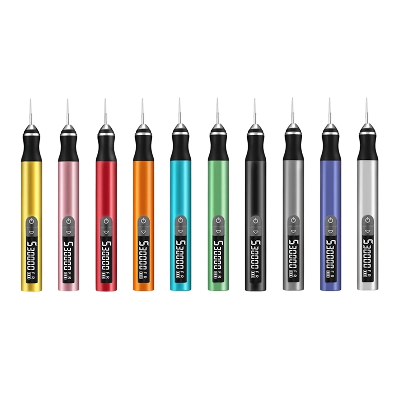
The H102's lightweight pen-style body can help with deliberate contact on an exposed raised remnant beside a detail. Its published plastic craft and model-making applications are relevant to that general task. They do not establish that every fine groove can be safely engraved. Confirm the exact attachment, material and speed instructions, including compatibility with the 2.35 mm chuck, before mounting anything.
Secure the model by a strong area without distorting the panel. Wear eye protection and use dust control suitable for the filament. Rehearse the path with the tool stopped, then test on comparable scrap. If supported by the tool and attachment instructions, make brief, light contacts on the isolated excess and stop to inspect. Do not run along the whole line to make its appearance uniform. Uniformity achieved by widening every groove is still a change to the model.
Account for plastic, wall thickness and finish
PLA can soften from concentrated friction, so a small contact area does not make heat irrelevant. PETG can leave strings or smears that conceal the original edge. ABS and ASA may permit useful mechanical finishing, but their print geometry and remaining wall still matter. A thin shell or flexible part does not gain a finishing allowance simply because the pen is set lower. This guide supplies no universal speed number.
The final finish also changes the decision. An unpainted colored model may show a conspicuous dull patch beside a cleaned line. On a painted model, primer can make scratches and irregular edges easier to see. Decide whether the visible improvement is worth touching a minor defect. When the current line reads clearly at normal viewing distance, preserving it may be preferable to chasing a perfectly smooth groove bottom.
Prepare for primer without filling the detail
After local cleanup, stop the tool and collect the debris. Inspect the panel in its relaxed state outside the fixture. Finish exposed edges by hand where that gives better control. Follow the coating manufacturer's preparation instructions for the actual plastic, and test the complete sequence on a representative spare part. Do not assume that a successful abrasive test also proves primer adhesion or solvent compatibility.
Apply coatings as their instructions specify, checking the detail between permitted stages. A heavy buildup can reduce the line's definition even when the plastic was originally correct. If filler is needed beside the groove, use a compatible product, allow its specified cure and finish it without cutting the surrounding detail. Do not rotary-sand an unknown coating or uncured filler to reopen a recess.
Stop before cleanup becomes resculpting
Widened corners, an uneven groove floor and a line that changes direction are signs that the finishing operation has crossed into reshaping. Further polishing may make the damage smoother without restoring its proportions. Compare the result with the untouched features nearby. If the change is unacceptable, a controlled cosmetic repair or reprint may be better than continuing around the model to make every line equally wide.
For the next version, consider the feature's width and depth relative to the intended print setup and paint system. A short test panel containing a straight section, a corner and an intersection can be more informative than repeatedly printing the whole prop. Record which issue occurred before paint and which appeared afterward. That distinction helps prevent a coating problem from being blamed on the printed geometry.
Frequently Asked Questions
Frequently Asked Questions
Can I use the engraving pen to trace every panel line?
Not as a general cleanup method. The available H102 information does not establish a controlled groove-tracing procedure for thin FDM details. Work only on a suitable isolated defect, or use the appropriate modeling and hand-finishing process.
Why does the line disappear after primer?
Possible causes include insufficient original depth and excessive coating buildup. Inspect a spare part through the same preparation and coating stages. Do not immediately deepen the whole model without identifying which stage changed the detail.
Should I sand the panel until a nearby pit is gone?
That removes sound material around the pit and can flatten neighboring features. A compatible cosmetic filler may suit a shallow nonfunctional defect. Significant wall damage or missing detail may justify reprinting instead.
Does a smaller bit always preserve more detail?
No. Check its full working profile, shank clearance, mounting and instructions. A tiny tip can still taper into the groove walls, produce a deep mark or hide the contact area from view.
How should I judge the finished recess?
Inspect it under angled light and at normal viewing distance, then compare its width and corners with the design. For a painted model, assess a test piece after the complete coating sequence, not just bare plastic.
Final Buyer Recommendation