
Electric Rotary Tool
Cleaning 3D Printed Threads: Keep the Fit, Remove the Burr
Cleaning 3D printed threads starts with identifying an isolated burr. Preserve the thread profile, clean accessible surrounding edges and avoid grinding away engagement.
Quick Answer
Cleaning 3D printed threads starts with finding what prevents engagement: debris, a raised print defect, a damaged thread start or an incorrect fit. A mini rotary tool may help remove an accessible burr on a surrounding face, but it should not be used to freehand recut the thread. Preserve the helix, clean the parts and test engagement gently by hand.
Buyer Takeaways
- Diagnose the first point of interference before choosing an abrasive.
- Keep rotary attachments away from the working thread flanks and roots.
- Test a printed screw and nut without power or forced tightening.
- Reprint a damaged or incorrectly sized thread instead of removing its engagement surfaces.
Identify the fastening system first
A printed screw-top lid, a hole for a self-tapping screw and a pocket for a metal threaded insert are not the same feature. Each has different geometry and assembly requirements. This article focuses on larger, accessible printed threads in noncritical FDM models and containers. It does not prescribe tapping, insert installation or repair of load-bearing fasteners. Follow the hardware manufacturer's instructions for those jobs.
Inspect the original design and confirm that the two parts belong together. Check their thread size, handedness and start position when that information is available. A thread that appears too tight might be a mismatched pair, a distorted print or a support defect. Grinding the entire circumference can hide the symptom while making the connection loose or unreliable. Remove loose dust and detached strings before deciding that solid material needs attention.
Read the way the parts begin to engage
With both pieces cool and clean, line them up and attempt gentle hand engagement. Stop at resistance instead of forcing a cap through it. Examine where contact occurs. A rough edge on the entrance face may catch before the thread starts. By contrast, resistance after part of a turn may come from a flank defect, ovality or a damaged section deeper inside. The location of resistance is a clue, not a complete diagnosis.
Look at the thread under good light and compare it with the model or an undamaged print. Is a bump visibly above the intended contour, or is the entire crest simply part of the thread? A seam can cross several turns; removing it aggressively can cut a channel through the helix. Mark the location on a photograph or sketch so you can return to the same spot without repeatedly forcing the parts together.
Technical Explanation
Preserve the working thread surfaces
A screw thread controls both rotation and axial movement. Removing a raised defect outside its working surfaces can improve entry, but removing a flank changes where the two parts carry contact. Therefore, an easier turning feel after sanding is not enough to establish a successful repair. Inspect engagement, alignment and play together. This guide addresses hobby fit checks and does not certify strength, sealing or repeated-service durability.
Keep the rotary work outside the working helix
A possible rotary task is a small raised remnant on a robust, exposed shoulder beside the thread, where removing it leaves the designed thread untouched. An attachment needs enough clearance that its sides and shank cannot graze the adjacent crest. If the tool must enter a narrow internal thread, or the contact point disappears behind the opening, hand inspection and a different method are preferable.
A flat entrance face is often better addressed with controlled hand sanding on a supported abrasive. A tiny accessible speck can sometimes be handled with a suitable fine file while preserving the surrounding shape. Do not improvise a thread cutter by pushing a rotary point into the groove. The H102 is not established here as a thread-chasing tool, and a visually smooth groove is not evidence that the original pitch or flank angle has survived.
Set up for one small, controlled correction
Remove large supports beforehand using an appropriate hand method. Secure the part on a strong unthreaded area, leaving the target visible. Avoid clamping across a thin threaded neck: it can become oval under pressure. Protect your eyes and collect dust at the work area. Keep the mating component elsewhere so debris cannot enter it while you work. Do not hold the cap in one hand beside a spinning bit.
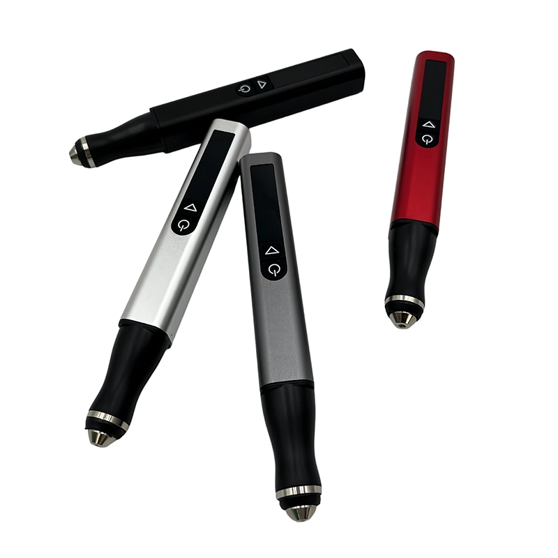
The H102's pen body can help locate contact on a small exposed shoulder. Its five adjustable gears allow a setting to be selected within the instructions for the confirmed attachment and material; they do not provide a verified thread-finishing recipe. Check compatibility with its 2.35 mm chuck, then trial the setup on matching scrap. Use light, brief contact and inspect frequently. Stop if the plastic smears, the attachment catches or the edge starts losing its intended shape.
Separate the material issue from the fit issue
PLA can soften at an abrasive contact through friction even when the rest of the part feels cool. Thin crests are particularly easy to damage. PETG may produce stubborn strings or smeared debris, so a rough-looking thread does not justify increasing pressure. ABS and ASA introduce their own printing and dimensional considerations. A part that shrank or warped will not become geometrically correct merely because its entrance was polished.
Flexible TPU threads need a separate assessment. Deformation during a fit test can resemble interference, and the H102 product page does not establish a TPU thread-finishing procedure. Filled filaments also need material-specific dust and accessory guidance. For all of these materials, stop if you cannot distinguish a local excess from the intended thread surface. A corrected model or printing process is preferable to a broad, uncontrolled removal operation.
Clean, release and check the full travel
After the tool has stopped, collect debris from the cleaned area and release the part from the fixture. Inspect the neck in its relaxed shape. Use a material-compatible cleaning method and allow the parts to dry as appropriate before assembly. Do not add a solvent or lubricant merely to conceal binding. Any lubricant must suit the material and application and should not substitute for diagnosing the fit.
Try the connection by hand again. Check whether it starts squarely, moves through its intended travel and reaches the designed stop without unusual force. Then check for excessive play. Passing only the first turn is not enough. A cap that now turns easily but rocks on the thread may have lost useful engagement. Before painting, protect the functional threads from coating buildup unless the design explicitly allows for the coating thickness.
Recognize when reprinting is the better finish
Missing thread sections, torn roots, repeated cross-threading, a visibly oval neck or insufficient wall thickness are reasons to stop this cleanup workflow. So is a need to remove material from most of the thread. A better next print may use a revised fit allowance, different orientation or improved support placement, depending on the printer, material and design. Make one controlled change and test a representative section where possible.
Formlabs' thread guide distinguishes printed threads, inserts and other fastening strategies. Its SLA and SLS dimensional examples should not be copied as universal FDM clearances. The useful principle here is to choose an appropriate fastening design and preserve the surfaces that perform the fastening. Rotary cleanup remains a limited operation around that design, not a way to invent a new thread profile by eye.
Frequently Asked Questions
Frequently Asked Questions
Can I grind an internal thread until the screw fits?
Do not use freehand rotary grinding as a general correction for an undersized thread. You can remove engagement unevenly and change alignment. Recheck the design and printing allowance, and use an appropriate machining process only where it is specified and supported.
Is a seam on every turn always a removable burr?
No. A seam may be raised, but nearby crests and flanks remain part of the designed thread. Inspect its actual profile. If cleanup would require following the whole helix with a rotary point, choose a different approach.
Can the H102 install a heat-set insert?
No heat-set insert installation method is established by this guide. Use the insert manufacturer's specified installation tool and procedure. A rotary pen's plastic-detailing applications do not make it a heat-installation tool.
Should I test the thread while it is clamped?
Make the final fit check with the print released and relaxed. Clamping can distort a hollow neck and give a misleading impression of fit. Keep any preliminary checks gentle and stop at resistance.
What if the thread fits before painting but binds afterward?
The coating may have changed the clearance. Avoid grinding through an unknown coating with the rotary pen. Review the paint manufacturer's preparation guidance and the design's coating allowance, then use a controlled correction appropriate to both materials.
Final Buyer Recommendation