
Rotary Tool and 3D Print Finishing
Rotary Pen Finishing for 3D Printed Architectural Models
Evaluate rotary pen finishing for 3D printed architectural models. Protect facade detail, roof edges and assembly datums while cleaning local print defects.
Quick Answer
Rotary pen finishing for 3D printed architectural models should stay local: a visible raised witness on a robust component or an accessible recess may justify evaluation. Keep facade relief, roof profiles, locating features and assembly edges protected. Judge the result both under close inspection and at the model’s intended viewing scale. Use hand methods or no removal where a rotating contact would obscure design detail or disturb assembly.
Buyer Takeaways
- Decide what the model communicates before chasing surface marks.
- Finish accessible components before assembly when the approved workflow allows it.
- Protect assembly datums as well as visible design detail.
- Approve the appearance at its intended viewing scale.
Start rotary pen finishing for 3D printed architectural models with the viewing brief
A presentation model is not simply a collection of smooth surfaces. Its roofline, facade rhythm, massing and relationship to the site communicate design. Ask the model owner which features must remain legible and where the viewer is expected to look. A mark hidden in the assembled base does not automatically deserve the same treatment as a raised defect interrupting a visible roof edge.
Formlabs describes architectural-model workflows that combine printed components with other materials and post-processing steps. That context supports a component-based finishing plan, not a claim that every architectural print needs a rotary pen. Keep the print material, preparation instructions and assembly method identifiable.
Create a small viewing brief: important faces, protected relief, visible seams, model scale and the intended color or coating. Use it to distinguish an unwanted artifact from a deliberate texture or an acceptable manufacturing trace. The purpose is a clear design presentation, not maximum material removal.
Clean a robust local feature without changing its silhouette
Evaluate a local pen operation only where the working contact can be seen and the component can be supported safely. A raised support witness on a substantial roof element may be a candidate; a fine parapet or slender column may require a small manual method or no intervention. The accessory’s contact footprint must fit the permitted region.
For an illustrative roof component, mark the witness and retain a side-view silhouette reference. Check the part with the tool stopped after limited work. Inspect whether the intended profile remains intact, not merely whether the mark is less noticeable. This is a sample exercise proposed for evaluation, not a reported ToolQeen result.
Avoid using a pen to chase shallow layer texture across a broad wall. Compare supported hand finishing where appropriate and preserve the wall’s plane. Stop when the operation starts to round an intended corner, blur facade lines or widen the cleaned area beyond the approved region.
Buyer Comparison
Match cleanup to the model requirement
| Component | Candidate role | Protected requirement |
|---|---|---|
| Robust roof element | Evaluate isolated witness cleanup | Silhouette and intended edges |
| Broad wall | Compare supported hand finishing | Plane and facade rhythm |
| Fine facade relief | Manual method or no removal | Detail at viewing scale |
| Assembly contact | Controlled preparation and fit check | Position and joint relationship |
| Site-model material transition | Inspect component preparation | Intended gap and surface treatment |
Separate facade details from removable artifacts
Inspect relief before choosing an accessory. Window reveals, fins and narrow separators can be important at presentation scale even when they look insignificant under bench magnification. Name those features in the protected-zone map. Do not let the tool kit’s available shapes determine which design details survive.
If an artifact lies between fine features, check the access path without power. Include clearance for withdrawal and inspection. A working point that only reaches the defect at a blind angle is a poor basis for a repeatable operation. Consider a shaped manual abrasive or a preparation change instead.
After cleanup, inspect the same area at the normal viewing distance as well as close up. Record whether the relevant design feature remains legible. A close-up cosmetic improvement can still fail the communication brief when it softens the edge that separates two elements.
Keep assembly edges and material transitions under separate control
A facade or roof may locate against a base, neighboring panel or nonprinted component. Identify those contact faces before finishing. A small unintended change can create an assembly gap even when the visible surface appears cleaner. Trial-fit the actual companion component using the model team’s required method.
When permitted by the workflow, finish accessible components before final assembly. Keep their identities and orientation clear. Do not grind an assembled seam to conceal a locating problem without first determining whether the parts were seated or prepared correctly. That would change the visible model without resolving the cause.
Coatings and bonding operations have their own material instructions. Retain the required preparation state and protect the relevant contact faces. This guide does not provide adhesive compatibility, paint thickness allowances, universal resin settings or a tolerance for architectural-model assembly.
Build the sample brief around presentation and assembly acceptance
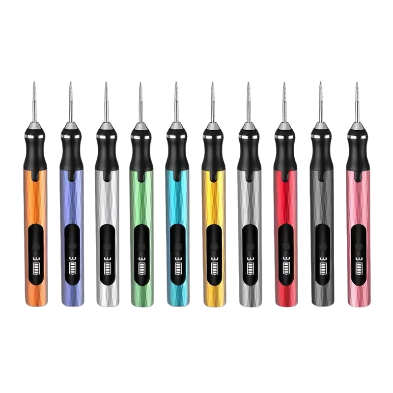
For a purchasing comparison, submit one representative robust feature and one delicate feature that should remain protected. Define the expected result for each. Ask the supplier for the actual pen, mounted accessory, interface and operating instructions; confirm what will be packed instead of assuming that a catalogue photograph establishes accessory contents.
Record the original condition, proposed method, protected design detail, close-up result, viewing-scale result and assembly check. Give the presentation owner the final decision. If the method works only on the robust feature, retain that limitation in the kit’s instructions.
A distributor can use this evidence to define a model-workshop assortment with meaningful roles. Confirm replacement working items, packaging, labeling, quantity basis and delivery separately. No reduction in model-making time or improvement in precision is claimed without comparable observed work.
Sources and application boundaries
Formlabs: Architectural models guide https://formlabs.com/global/blog/3d-printing-architectural-models/ Component-based architectural modeling and post-processing context; not a ToolQeen tool evaluation.
ToolQeen Quality evidence path https://www.toolqeen.com/quality Exact configuration, method and approval traceability; not an application-specific test.
Frequently Asked Questions
Frequently Asked Questions
Should a hidden print mark be removed?
Decide against the assembly and presentation requirements. Removing a harmless hidden mark can introduce risk without improving the model.
Who should approve the viewing-scale result?
The model or design-presentation owner, using the agreed viewing brief. A tool operator’s close-up judgement is only one part of the decision.
Can a tool repair a model detail that did not print?
An abrasive cannot add missing geometry. Refer the defect to the model team for an approved repair or reprint rather than removing neighboring detail.
Should every model component use the same finishing setting?
No. Material, preparation, accessory and feature conditions need their own qualified method. This article prescribes no universal RPM.
What should a tool sample photograph include?
The identified component, original defect, protected region and the finished result at both inspection and viewing scales, with the actual configuration recorded separately.
Final Buyer Recommendation