
Rotary Tool and 3D Print Finishing
3D Printed Enclosure Finishing: Fit, Edges and Paint Prep
Plan 3D printed enclosure finishing around lid fit, openings and paint preparation. Learn where a mini rotary tool helps and where files or sanding blocks work better.
Quick Answer
Good 3D printed enclosure finishing preserves the lid seat, openings and fastener features while removing unwanted protrusions. Dry-fit the empty parts first, identify the exact obstruction and remove only that excess. Use a mini rotary tool for suitable accessible high spots, a file for controlled edges and a sanding block for flat faces. Recheck fit before filler, primer or paint.
Buyer Takeaways
- Find the contact point before enlarging an opening or sanding a whole edge.
- Keep electronics out of the enclosure while generating dust.
- A smooth surface and a correct mechanical fit are separate outcomes.
- Coatings add thickness, so protect mating and fastening features.
Start with an empty enclosure and a fit check
A lid that rocks, a rough cable opening and a scarred exterior can look like one finishing problem. They are three different jobs. Successful 3D printed enclosure finishing begins by separating fit, handling and appearance so that improving one does not damage another.
Let the printed halves cool and check them without electronics installed. Note which surfaces are intended to touch, which need clearance and which will be visible. Keep the drawing or CAD model nearby if available. Inspect thin walls, screw bosses and snap features for cracks or poor layer bonding before attempting to improve the finish.
Place the lid on the base without forcing it. A local support remnant may hold one corner high; a warped rim or globally undersized lid is a different problem. Do not grind all four edges simply because one corner fails to close. Persistent distortion may be better corrected in the design or print process.
Map the defects to the surfaces you must preserve
Mark the location of each visible high spot with a removable method that will not affect the planned coating. Inspect under side lighting and compare with the intended contour. An isolated bump above a rim can be removed; a depression below an exterior face may need compatible filler. Removing sound material around a pit makes the wall thinner.
Separate three zones: the external cosmetic face, the mating rim and the hardware features. A flat face benefits from an evenly supported abrasive. A rim requires small, controlled adjustments followed by another fit check. A screw boss or snap tab should retain its designed shape and thickness.
For a cable or switch opening, distinguish a rough protrusion from an opening that is dimensionally wrong. A deburring pass removes excess on an edge; it is not a reliable substitute for measuring and redesigning a port. Do not turn a round hole into an oval while trying to make a connector fit.
Technical Explanation
Finishing changes dimensions as well as appearance
Removal enlarges an opening or reduces a wall; filler and paint add material. Keep functional contact surfaces separate from cosmetic repairs. Repeated dry-fitting at defined checkpoints catches a fit change before coating makes the cause harder to see.
Assign the right tool to each small job
A fine hand file is useful for taking down a localized straight edge while watching its alignment. Abrasive paper on a flat block helps preserve a broad lid or side panel. On an external corner, use a small supported piece of paper to remove a sharp burr without creating a large chamfer.
A mini rotary tool can help with an accessible raised support remnant on a substantial wall or a local inside curve. It needs room for the working head and chuck, a clear view of the contact and a secure way to hold the enclosure. A tight recess beside a thin boss may fail those requirements even if a pointed bit can physically reach it.
Do not use a freehand rotary head to size precision holes, chase printed threads or reshape a snap latch. Do not apply a cutoff wheel sideways to smooth a face. If the tool or accessory instructions do not support the operation, choose a hand method or revise the part.
Remove supports, fixture the shell and test
Remove large supports with appropriate hand tools before powered finishing. Support the enclosure near the contact area and take small sections away rather than twisting against the wall. Wear eye protection during clipping as well as sanding. Keep all circuit boards, switches and batteries away from the dust-producing work.
Secure the shell in padded jaws or a fixture that supports a robust region. Check that it cannot slide, rotate or flex into the accessory. Set up extraction suitable for fine plastic dust, and follow the filament and abrasive guidance for respiratory protection. Do not blow debris through an enclosure that contains components.
Use a matching scrap print to test the proposed accessory and setting. Confirm the chuck fit, the accessory's permitted speed and plastic use, and the way it must be mounted. Switch the tool off and disconnect charging power for changes. A small trial should show controlled removal without chatter, softened edges or damage to the surrounding wall.
Correct one interference point, then dry-fit again
With the part secured and the contact point visible, remove only a small amount from the raised remnant. Use light, brief contact with an approved accessory, lift away and inspect. Allow cooling between passes. PLA can soften from friction; a PETG part still requires its own trial rather than a faster assumed setting.
Stop short of the finished contour and use a hand file or paper for the final blend. Clear loose debris before each fit check, since a fragment trapped under the lid can mimic a remaining interference. Compare the gap around the enclosure without forcing the lid closed.
If removing the identified nub does not improve the fit, reassess the cause. Check whether the lid is warped, the rim is uneven or the designed clearance is inadequate. More grinding at the original spot may create a gap without fixing the real obstruction. A sound enclosure should close as intended while retaining sufficient material around its fastening features.
Prepare cosmetic faces for primer and paint
Once the fit is satisfactory, turn to the exterior. Blend rough areas with an appropriate hand abrasive and support flat surfaces with a block. Avoid rounding the lid seam or erasing embossed labels. A uniformly dulled surface is not proof that every scratch has disappeared; inspect with the dust removed and the part dry.
For recessed support scars or assembly seams that should disappear, select a filler compatible with the filament and coating. Follow its preparation, thickness, cure and sanding instructions. Do not fill vents, screw holes or intentional gaps. Prusa's post-processing guide illustrates the separate roles of sanding, filling and primer; the specific coating manufacturer's instructions should govern the products you choose.
Clean the part as directed by the coating supplier and allow it to dry completely. Test adhesion and appearance on matching scrap before painting the enclosure. Mask or otherwise protect mating rims, threads, snap features and surfaces where extra coating thickness could change fit. Use the ventilation and protective equipment required by the coating instructions.
Inspect the enclosure before installing components
After coatings have cured as instructed, remove masking carefully and check the lid again. Look inside openings for trapped dust, abrasive fragments or dried residue. Inspect screw bosses and thin edges for cracks or excessive removal. Confirm that the original fasteners still align without forcing the parts together.
Check the edge that a cable will pass over with the enclosure empty. The intended result is a clean edge and the protection specified by the design, such as an appropriate grommet; cosmetic smoothing does not replace strain relief or electrical protection. This finishing guide does not qualify a printed box for mains voltage, high temperatures or a certified safety function.
If the part has become too thin, an opening too large or a latch damaged, stop and replace or redesign it. Paint and filler can improve appearance but cannot be assumed to restore a load-bearing feature. Install components only after the enclosure is clean, dry and mechanically ready.
Choose an H102 configuration for local cleanup
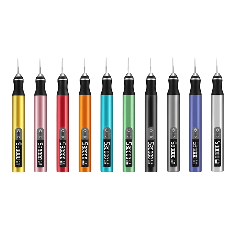
The ToolQeen H102 Cordless Electric Engraving Pen lists plastic carving and model-making applications. Its 59 g pen body is relevant when you need to place a small working tip near a visible high spot, and its five speed levels and digital display help identify the selected setting during a trial.
The specifications list a 2.35 mm metal chuck and a maximum speed of 30,000 RPM. The public page does not provide a minimum speed, per-step RPM values or verified PLA/PETG finishing settings. A set of 30 accessories is listed, but a specific sanding head's inclusion and suitability must be confirmed. These limitations matter more than the maximum speed when the wall is thin.
Use the product link to review the H102 and ask about an appropriate accessory for your filament, defect and available clearance. Include photos of the empty part and identify surfaces that must retain their dimensions. ToolQeen uses a quotation and inquiry route; ask about sample or individual-unit availability if you are buying for a home workshop.
Frequently Asked Questions
Frequently Asked Questions
Should I sand the lid or the enclosure body when they do not fit?
Identify the actual contact point first. Remove a clearly unwanted protrusion from that location, then check again. If the problem is a warped rim or inadequate designed clearance, indiscriminate sanding of either half may create uneven gaps without fixing the cause.
Can a rotary tool enlarge a connector opening accurately?
Freehand grinding can change the shape as well as the size. For a minor burr, use a controlled hand method. For an undersized port, check the design and dimensions and consider revising the print. Do not use this cleanup procedure as a precision machining method.
Should I fill support scars before checking assembly fit?
Check fit first. Filling is for a recessed cosmetic defect on a sound part, not for hiding a mechanical problem. Keep filler clear of intentional gaps and hardware interfaces. Recheck fit after coatings have cured because they can add thickness at the edges.
Can I finish the enclosure with electronics still inside?
Remove the components before dust-producing work whenever the design permits it. Keep electronics and batteries away from the finishing bench. Clean and inspect the empty enclosure thoroughly before reassembly; a smooth exterior says nothing about debris trapped inside.
Is the H102 suitable for every enclosure material?
No. The H102 lists plastic and model-making applications, but it does not publish validation for every filament or accessory combination. Confirm the exact material and head. Flexible, filled, unusually thin or safety-critical parts need separate assessment.
Final Buyer Recommendation