
Rotary Tool and 3D Print Finishing
3D Printed Vacuum Forming Mold Cleanup: Keep the Geometry
Scope 3D printed vacuum forming mold cleanup to local defects. Protect vents, draft and radii, and keep tool approval separate from forming-process validation.
Quick Answer
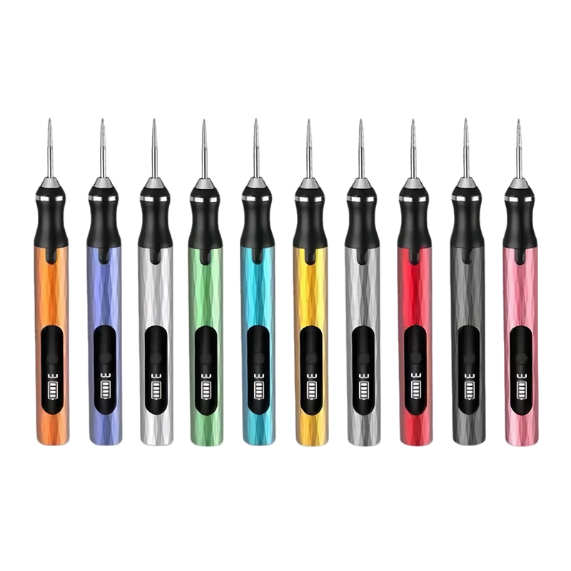
3D printed vacuum forming mold cleanup should address a named local artifact while preserving designed draft, radii, vent features and seating geometry. A rotary pen may be evaluated for an accessible raised witness on a qualified printed mold, but it is not a substitute for mold design or controlled vent machining. Inspect affected features before a forming trial. Tool-sample acceptance does not establish thermal suitability, forming quality or mold service life.
Buyer Takeaways
- Start with a mold design and material already evaluated for the forming process.
- Keep vent cleaning separate from changing vent geometry.
- Preserve designed radii, draft surfaces and seating features.
- Qualify the forming result separately from local tool cleanup.
Define the boundary of 3D printed vacuum forming mold cleanup
Begin with the mold revision, material identity and forming team’s approved preparation procedure. The purchasing question here is whether a small unwanted artifact can be removed without changing the tooling. It is not whether any printed material can become a vacuum-forming mold after sanding.
Formlabs documents printed thermoforming tooling and identifies vents, preparation and mold geometry as part of the workflow. That guidance is material- and process-specific. It does not establish a thermal capability, forming-cycle limit or application approval for a ToolQeen tool or a buyer’s printed mold.
Mark the contact surface, draft faces, radii, vent features and locating or seating regions. Identify the defect independently of these designed features. If the actual issue is wrong geometry or unqualified material, return it to the tooling and process owners before selecting a finishing accessory.
Evaluate local witness removal on a spare or approved test region
A visible raised witness in a robust accessible region may be a reasonable candidate for sample evaluation. Verify the pen and accessory instructions, interface and permitted operation. Support the mold without distorting its locating relationship, and check access with the tool off. Keep the contact within the named region.
For an illustrative prototype mold, identify a small raised witness away from a designed corner and retain its original contour reference. Inspect after limited work with the tool stopped. The acceptance question is whether the excess has been addressed without disturbing the contact surface or neighboring feature. This is a proposed exercise, not a reported ToolQeen forming trial.
Broad surface correction, intentional radius changes and dimensional repairs need their own approved process. Do not use local rotary cleanup to hide a mold-design issue or to establish a new draft angle by eye. A visual improvement cannot substitute for the required tooling geometry.
Buyer Comparison
Keep tooling decisions with the correct evidence
| Question | Required evidence | What a pen sample cannot prove |
|---|---|---|
| Local witness removed? | Before/after feature inspection | Whole-mold qualification |
| Vents remain correct? | Drawing and preparation checks | Correct geometry from tool fit |
| Draft and radii preserved? | Approved design reference | New geometry by visual smoothing |
| Mold seats correctly? | Actual setup inspection | Thermal or forming suitability |
| Formed part accepted? | Process-owner trial evidence | Yield or service life |
Treat vents as designed features rather than convenient tool openings
Identify what each vent is intended to do and how the forming team inspects it. Formlabs describes cleaning printed air vents and channels during its specified preparation workflow. Follow the applicable material and tooling instructions; a rotating point is not automatically the correct way to clear a passage.
Distinguish debris or a preparation residue from an undersized, blocked-by-design or incorrectly placed feature. Removing debris and enlarging a vent are different operations. Do not push an abrasive into a passage simply because it fits. An unapproved change may alter the feature without solving the actual cause.
Use the drawing and inspection plan for dimensional acceptance. If intentional vent machining is required, assign the appropriate controlled process and record its result. The pen can remain a candidate for an approved local exterior task without being presented as a vent-drilling system.
Check draft faces, corner transitions and mold seating after cleanup
Inspect affected surfaces against the approved design reference. Keep intentional radii and corner transitions separate from unwanted protrusions. A small accessory can reach an edge yet leave a contour that differs from the required shape. Record any collateral mark instead of describing all removal as successful finishing.
Check the locating and seating relationship with the actual forming setup under the responsible team’s method. Do not alter a base or contact face to make a mold appear to fit without establishing the cause of the mismatch. Forming equipment, material preparation and installation remain separate controlled conditions.
If an inspector cannot tell whether the tool operation changed a critical feature, hold the mold for clarification. Repeated cosmetic passes are not a valid response to missing measurement or an unclear acceptance rule.
Keep the mechanical sample and the forming trial as separate decisions
An accepted local cleanup can show that the named artifact was addressed under a defined method. It cannot establish the material’s suitability for heat, the formed part’s acceptance, or repeated-use life. The process owner needs the actual forming conditions and relevant supplier evidence for those decisions.
For an equipment buyer, request the exact pen, mounting interface, working item and instructions evaluated on the sample. List protected tooling features and excluded operations in the brief. Confirm packed configuration, spare-item references and commercial terms rather than relying on the largest assortment count.
Retain the local cleanup record alongside the mold revision and any downstream forming record. Changes to material, geometry, accessory or process require review of the affected evidence. This article provides no promised cycle count, uniform finish, heat resistance or production yield.
Sources and application boundaries
Formlabs: Thermoforming https://formlabs.com/support/Thermoforming/ Material-specific tooling, vent preparation and forming workflow context; no ToolQeen performance is inferred.
ToolQeen Quality evidence path https://www.toolqeen.com/quality Exact configuration, method and approval traceability; not an application-specific test.
Frequently Asked Questions
Frequently Asked Questions
Does sanding make ordinary filament suitable for forming heat?
No. Surface finishing does not establish thermal or process suitability. Use the material and forming-process owner’s qualification evidence.
Can the pen be used to enlarge every printed vent?
No. Intentional vent changes require the approved drawing, method and inspection. Physical access alone does not authorize enlargement.
Should a forming defect trigger more grinding?
Diagnose the material, mold geometry, preparation and forming setup first. Further removal is appropriate only for a named approved correction.
What must the supplier quote identify?
The pen, working accessories, interface, instructions, included spares, packaging and confirmed commercial basis. Keep thermal tooling approval outside the tool quotation.
Can a local cleanup sample support a mold-life claim?
No. Repeated forming performance needs its own defined process and observed evidence. This guide reports no measured mold lifetime.
Final Buyer Recommendation